Compressor device

A technology of compressors and driving devices, which is applied to pump devices, mechanical equipment, components of pumping devices for elastic fluids, etc., and can solve problems such as changes in oil supply

Active Publication Date: 2017-11-28
ATLAS COPCO AIRPOWER NV
View PDF8 Cites 0 Cited by
  • Summary
  • Abstract
  • Description
  • Claims
  • Application Information

AI Technical Summary

Problems solved by technology

[0016] Also, switching between the pump and the auxiliary pump will result in a change in the oil supply

Method used


Image

  • Compressor device
  • Compressor device
  • Compressor device

Examples


Embodiment Construction

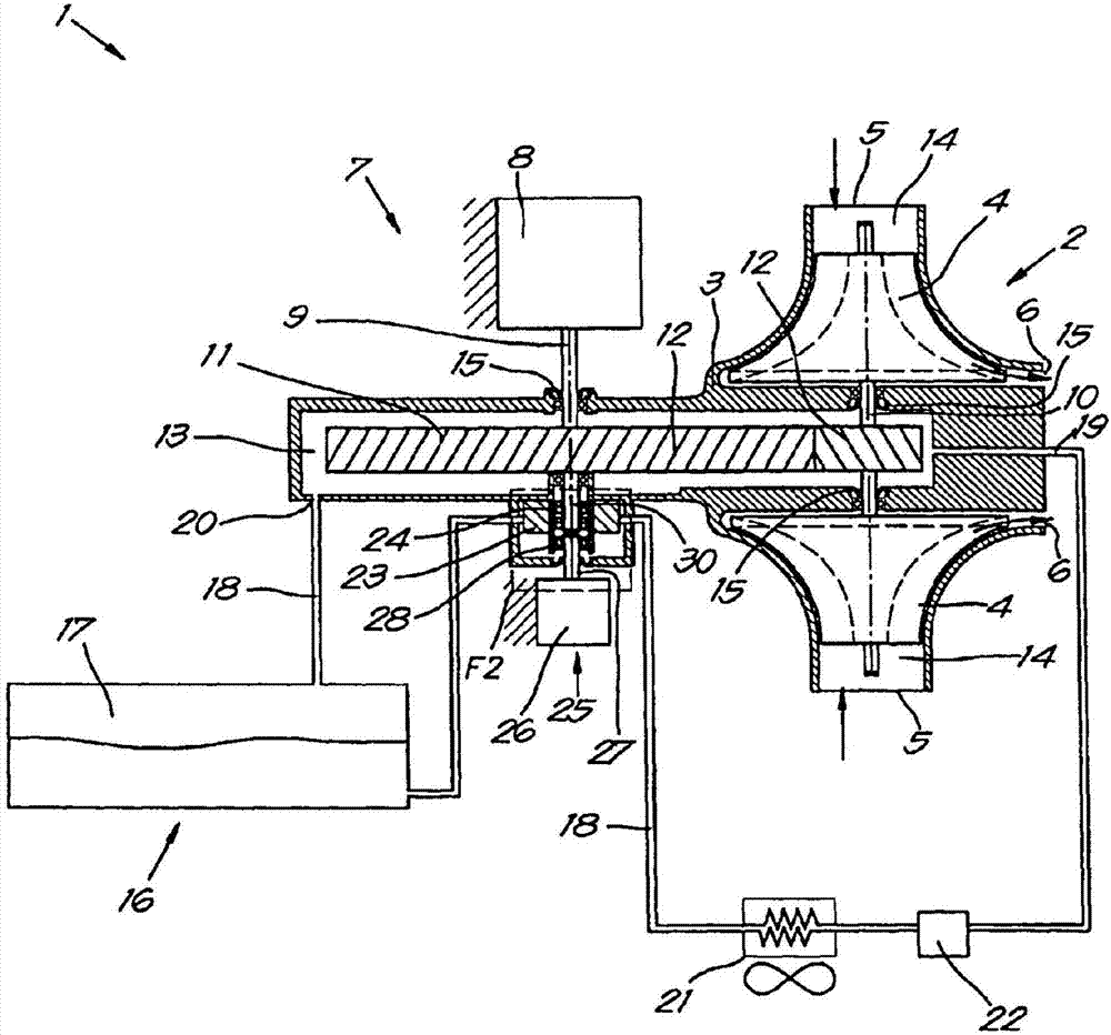
[0041] exist figure 1 The compressor arrangement 1 shown in FIG. 2 comprises a centrifugal compressor element 2 having a housing 3 in which in this case two rotors in the form of impellers 4 are fixed.

[0042] It is clear that the compressor arrangement 1 may comprise different types of compressor elements 2, such as eg screw compressor elements or turbo compressor elements.

[0043] The housing 3 is provided with an inlet 5 for the gas to be compressed and an outlet 6 for the compressed gas.

[0044] A drive 7 is provided for driving the impeller 4 .

[0045] This drive 7 comprises a motor 8 having a first shaft 9 coupled to the shaft 10 of the impeller 4 via a transmission 11 .

[0046] In this case, this transmission 11 comprises a gear wheel 12 fixed on the first shaft 9 and on the shaft 10 of the impeller 4 .

[0047] if possible in figure 1 As observed in , the transmission 11 is integrated in a space 13 in the housing 3 which is isolated from a space 14 in the hous...


PUM


Abstract

A compressor device for compressing gas comprises a compressor element (2) with a housing (3) with, an inlet (3) and an outlet (6), whereby at least one rotor is affixed in the housing (3) that is provided with a drive (7), whereby the compressor device (1) is provided with an oil circuit (16) for injecting oil into the housing (3) f characterised in that the oil circuit (16) only comprises one pump (23) for driving the oil around in the oil circuit (16), whereby this pump (23) is coupled to a first shaft (9) via a first disengageable coupling (24), more specifically a shaft (9) of the aforementioned drive (7) on the one hand, and to a second shaft (27) via a second disengageable coupling (28), more specifically a shaft (27) of a secondary drive (25) on the other hand, whereby the first and second disengageable couplings (24, 28) between the pump (23) and the first shaft (9) and between the pump (23) and the second shaft (27) are such that the pump (23) is only driven by the shaft of these two shafts (9, 27) that has the highest speed.

Description

technical field [0001] The invention relates to a compressor device. [0002] More particularly, the invention relates to a compressor device for compressing a gas, said compressor device comprising a compressor element having a housing with an inlet and an outlet, wherein at least one rotor is fixed in a In the casing of the driving device, the compressor device is provided with an oil passage for injecting oil into the casing. [0003] The rotor may for example be a screw rotor, in which case the rotor is a screw compressor element or when it concerns a centrifugal compressor element the rotor is eg an impeller or a compressor wheel. Background technique [0004] It is known to cool and / or lubricate compressor elements using oil injected into the casing of the compressor element. [0005] The oil is guided through the compressor unit by an oil circuit. [0006] In order to be able to inject oil, the oil circuit is provided with an oil pump. [0007] The oil pump is dri...

Claims


Application Information

Patent Timeline
Patent Type & Authority Applications(China)
IPC IPC(8): F04C28/06F04C29/02F04D13/02F04D25/02F04D29/063
CPCF04C28/06F04C29/025F04D13/021F04D25/02F04D29/063F04D17/10
Inventor K·皮特斯
Owner ATLAS COPCO AIRPOWER NV
Why Eureka
Try Eureka