Semiautomatic manual hydraulic valve

A hydraulic valve, semi-automatic technology, applied to valve details, valve devices, engine components, etc., can solve problems such as single structure, and achieve the effect of convenient and fast switching flow direction

Inactive Publication Date: 2017-07-04
NINGBO HAIHONG HYDRAULICS
View PDF0 Cites 0 Cited by
  • Summary
  • Abstract
  • Description
  • Claims
  • Application Information

AI Technical Summary

Problems solved by technology

However, the existing manual reversing valve has a single structure and cannot solve some common problems while using the manual reversing valve

Method used


Image

  • Semiautomatic manual hydraulic valve

Examples


Embodiment Construction

[0011] The specific implementation manners of the present invention will be further described in detail below in conjunction with the accompanying drawings and embodiments. The following examples are used to illustrate the present invention, but are not intended to limit the scope of the present invention.

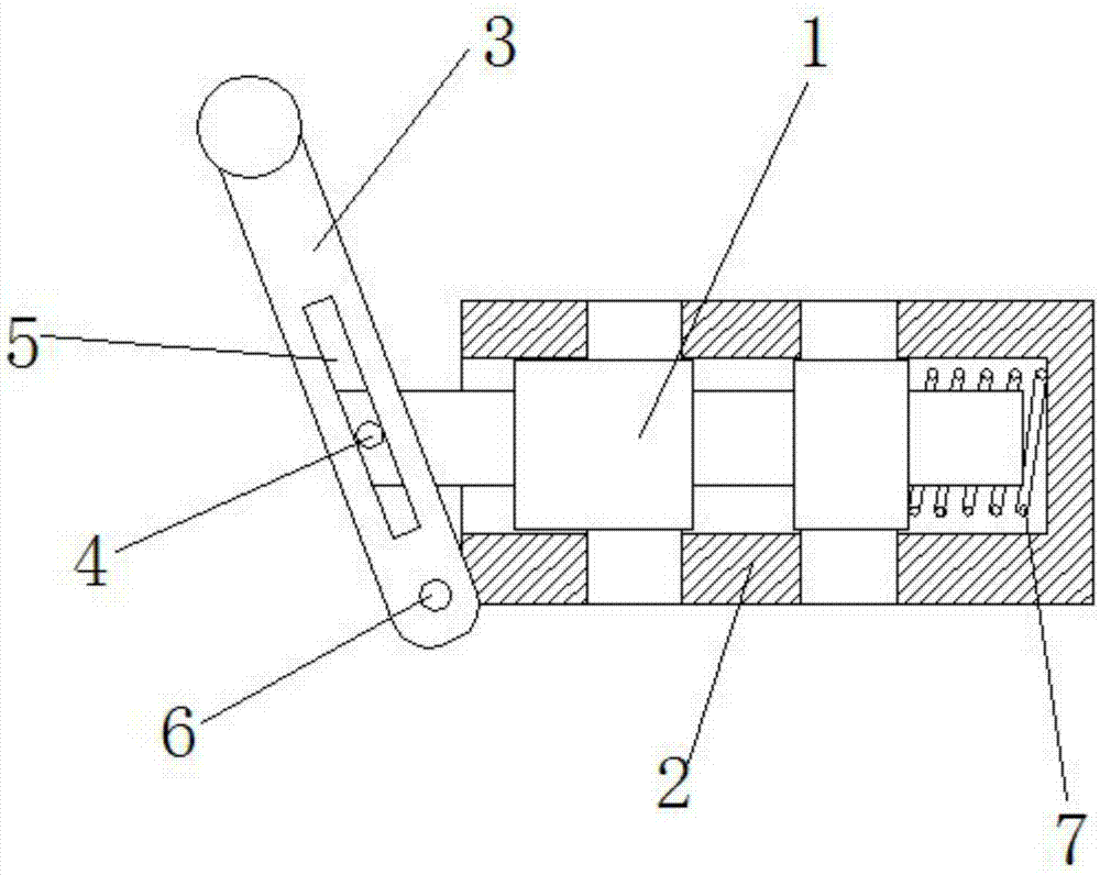
[0012] The structure of a kind of semi-automatic manual hydraulic valve of the present invention is as figure 1 As shown, it includes a valve housing 2, a valve core 1, a handle 3 and a spring 7. The valve core 1 is installed in the valve housing 2, and the rear end of the valve core 1 is provided with a spring installation position. The spring 7 Installed on the spring installation position, the handle 3 is installed on the other end of the valve core 1 and connected with the valve core 1, one end of the spring 7 is connected with the valve core 1, and the spring 7 The other end of the spring 7 is connected to the valve casing 2, and the spring 7 is used to push the valv...


PUM


Abstract

The invention discloses a semiautomatic manual hydraulic valve which comprises a valve casing, a valve element, a handle and a spring. The valve element is mounted in the valve casing. The spring is mounted at one end of the valve element. The handle is mounted at the other end of the valve element. The spring is located between the valve element and the valve casing. According to the semiautomatic manual hydraulic valve, the flow direction can be conveniently and fast switched through the handle, in addition, the valve element can be automatically returned without control of the handle, and it is guaranteed that a reversing valve is in a closed state.

Description

technical field [0001] The invention relates to the field of reversing valves, in particular to a semi-automatic manual hydraulic valve. Background technique [0002] The reversing valve is a directional control valve with more than two flow forms and more than two oil ports. It is a valve that realizes communication, cutting and reversing of hydraulic oil flow, as well as pressure unloading and sequential action control. Manual reversing valves are often used in hydraulic control systems to manually control the flow direction of hydraulic oil. However, the existing manual reversing valve has a single structure and cannot solve some common problems while using the manual reversing valve. Contents of the invention [0003] (1) Technical problems to be solved [0004] Aiming at the deficiencies in the prior art, the present invention provides a semi-automatic manual hydraulic valve. [0005] (2) Technical solutions [0006] In order to achieve the above object, the prese...

Claims


Application Information

Patent Timeline
Patent Type & Authority Applications(China)
IPC IPC(8): F16K31/60F15B13/02
CPCF16K31/60F15B13/02
Inventor 邓波
Owner NINGBO HAIHONG HYDRAULICS
Why Eureka
Try Eureka