
Waste heat recovery type sintering cooling equipment

A technology for cooling equipment and waste heat recovery, which is applied to lighting and heating equipment, charge processing types, furnace cooling, etc., and can solve the problems of high energy consumption and waste of heat energy for air cooling

Active Publication Date: 2021-06-08
山西博宇重工股份有限公司
View PDF18 Cites 0 Cited by
  • Summary
  • Abstract
  • Description
  • Claims
  • Application Information

AI Technical Summary

Problems solved by technology

[0005] In order to solve the technical problems in the prior art that mainly rely on air cooling to dissipate heat in the background technology, but the energy consumption of air cooling is high, and a large amount of heat energy is wasted in vain, the present invention proposes a waste heat recovery type sintering cooling equipment, which has the ability to cool The heat source in the process generates electricity and reuses it, which is more energy-saving and environmentally friendly.

Method used


Image

  • Waste heat recovery type sintering cooling equipment
  • Waste heat recovery type sintering cooling equipment
  • Waste heat recovery type sintering cooling equipment

Examples


Embodiment Construction

[0025] In order to make the object, technical solution and advantages of the present invention clearer, the present invention will be further described in detail below in combination with specific embodiments and with reference to the accompanying drawings. It should be understood that these descriptions are exemplary only, and are not intended to limit the scope of the present invention. Also, in the following description, descriptions of well-known structures and techniques are omitted to avoid unnecessarily obscuring the concept of the present invention.

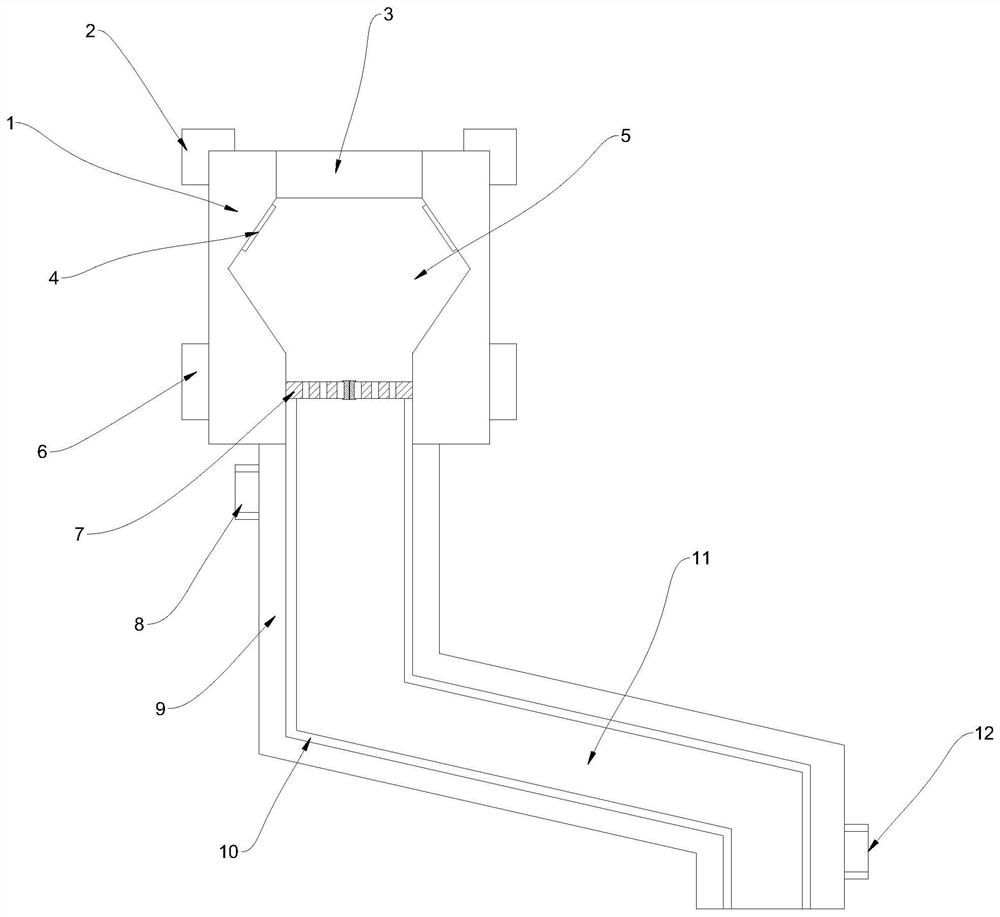
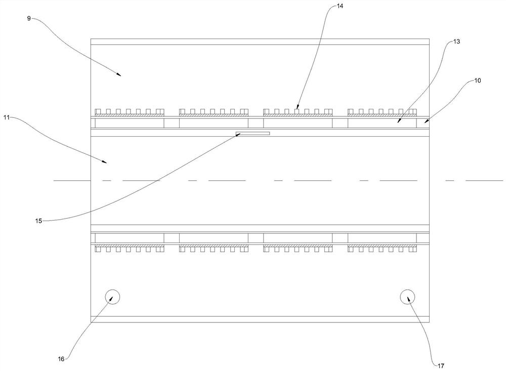
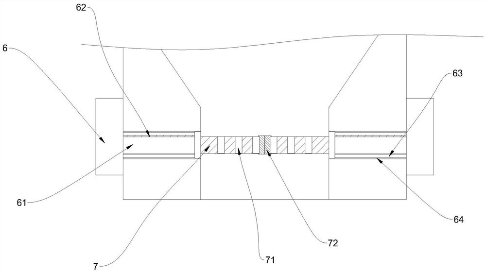
[0026] Such as Figure 1-3 As shown, a waste heat recovery type sintering cooling device proposed by the present invention includes a receiving hopper 1, a feeding pipe 11 and a water storage chamber 9;

[0027] The top of the hopper 1 is provided with a feeding port 3, and the hopper 1 is provided with a conical cooling pipe 5; the conical cooling pipe 5 communicates with the feeding port 3;

[0028] The water storage ...


PUM


Abstract

The invention relates to the technical field of cooling equipment, in particular to waste heat recovery type sintering cooling equipment. The waste heat recovery type sintering cooling equipment comprises a receiving hopper, a conveying pipe and a water storage cavity; a feeding port is formed in the top of the receiving hopper, and a conical cooling pipe is arranged in the receiving hopper; the conical cooling pipe communicates with the feeding port; the water storage cavity is formed in the top of the receiving hopper; a water inlet is formed in the bottom of the water storage cavity, and a water outlet is formed in the top of the water storage cavity; the conveying pipe penetrates through the water storage cavity; driving motors are arranged on the left side and the right side of the receiving hopper, and a mounting cavity is formed in the receiving hopper; transmission lead screws are arranged at the output ends of the driving motors; a partition plate is arranged on a guide rod in a sliding mode; an interlayer is arranged between the water storage cavity and the conveying pipe; cooling fins are arranged at the cold end of a thermoelectric power generation sheet, and the cooling fins are inserted into the water storage cavity; and the hot end of the thermoelectric power generation sheet is tightly attached to the outer wall of the conveying pipe, and the hot end of the thermoelectric power generation sheet is coated with heat conduction silicone grease. According to the waste heat recovery type sintering cooling equipment, a heat source in the cooling process can be generated and repeatedly utilized, so that more energy is saved, and the environment is protected.

Description

technical field [0001] The invention relates to the technical field of cooling equipment, in particular to a waste heat recovery type sintering cooling equipment. Background technique [0002] The iron and steel industry is an important basic industry of the national economy. Its development level has become an important symbol to measure the comprehensive national strength of a country. It mainly includes the production of mining, mineral processing, sintering, coking, ironmaking, steelmaking, steel rolling, metal products and auxiliary materials. Among them, the sintering process is a more important process, and the cooling device is a more important part of the sintering process. Although the functions of the existing energy-saving cooling devices for steel sintering are gradually improving, there are still some deficiencies that need to be improved. In the prior art, air cooling is mainly used to dissipate heat, but the energy consumption of air cooling is high, and a la...

Claims


Application Information

Patent Timeline
IPC IPC(8): F27D9/00F27D17/00H02N11/00
CPCF27D9/00F27D17/004H02N11/002F27D2009/0075F27M2003/04Y02P10/25
Inventor 成浩
Owner 山西博宇重工股份有限公司
Learn More