
Dual directional antenna beacon device, system and method with controllable emission direction

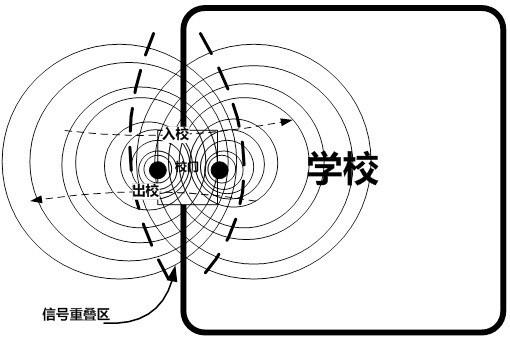
A technology of transmitting direction and directional antenna, applied in the antenna combination, antenna, antenna coupling and other directions with different interactions, it can solve the problems of information false alarm, interference, etc., to prevent signal harassment, improve signal recognition, and solve mutual interference. Effect

Active Publication Date: 2020-09-08
成都新橙北斗智联有限公司
View PDF3 Cites 0 Cited by
  • Summary
  • Abstract
  • Description
  • Claims
  • Application Information

AI Technical Summary

Problems solved by technology

[0008] The purpose of the present invention is to overcome the deficiencies of the prior art, and provide a Beacon device, system and method with dual directional antennas with controllable emission directions, so as to at least solve the problem of interference caused by overlapping signals when multiple Beacon devices are used at the same time. Prevent problems such as false positives, omissions, and misstatements of information

Method used


Image

  • Dual directional antenna beacon device, system and method with controllable emission direction
  • Dual directional antenna beacon device, system and method with controllable emission direction
  • Dual directional antenna beacon device, system and method with controllable emission direction

Examples


Embodiment Construction

[0030] The technical solution of the present invention will be further described in detail below in conjunction with the accompanying drawings, but the protection scope of the present invention is not limited to the following description.

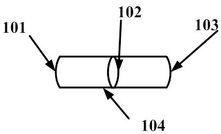
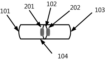
[0031]A dual directional antenna Beacon device with controllable emission direction, which includes two Beacon transmitting modules, a metal directional shield and a directional antenna spacer, the Beacon transmitting module includes an antenna, and the metal directional shield is provided with two Directional opening, the two Beacon transmitting modules and the directional antenna spacer are arranged on the metal directional shield, the directional antenna spacer separates the metal directional shield into two spaces, and the two Beacon transmitting modules are respectively arranged on the directional antenna isolation On both sides of the sheet, the antenna mounting surfaces of the two Beacon transmitting modules are respectively facing th...


PUM


Abstract

The invention discloses a bi-directional antenna Beacon device with a controllable emission direction, a system and a method. The device comprises two Beacon emission modules, a metal directional shielding body and a directional antenna separation sheet. The Beacon emission module comprises an antenna. Two directional openings are arranged in the metal directional shielding body. The Beacon emission modules are arranged on two sides of the directional antenna separation sheet. Antenna assembling faces of the Beacon emission modules face corresponding directional openings of the metal directional shielding body. The system comprises a Beacon signal directional emission end and a Beacon signal directional receiving end. In the method, the emission of Beacon signals is adjusted through the metal directional shielding body, and multi-azimuth reception is achieved through the Beacon device. According to the invention, a problem of mutual interference caused by overlapping of signal covering regions is solved, and signal recognition degree is improved.

Description

technical field [0001] The invention relates to the field of bluetooth communication, in particular to a Beacon device, system and method with controllable emission directions and dual directional antennas. Background technique [0002] Ordinary Beacon is a broadcast protocol based on the low-power Bluetooth protocol, and it is also a low-power Bluetooth device (slave) with this protocol. As a Beacon device, it is usually placed in a fixed position indoors or outdoors, so as to continuously broadcast to the surroundings. However, the antenna of a conventional Beacon is non-directional, centering on the Beacon arrangement point, and covering the surrounding space in the form of a circular area or a fan-shaped area. Such a design has a very large overlapping area of ​​signal coverage of multiple different nodes in some specific application scenarios, which is likely to cause mutual interference and lead to false positives, missed negatives, and false positives. [0003] The ...

Claims


Application Information

Patent Timeline
Patent Type & Authority Patents(China)
IPC IPC(8): H01Q1/52H01Q19/02H01Q21/29
CPCH01Q1/521H01Q1/526H01Q19/02H01Q21/293
Inventor 荣发文雷子钒明园
Owner 成都新橙北斗智联有限公司
Learn More