
Eureka
For R&D, Eureka makes reading and utilizing patents & technical documents easy.
Eureka AIR
Designed for self-driven R&D workflows. Generate viable solutions, solve complex R&D challenges, empower your innovation with AI.

Eureka Materials
Designed for material experts only. Revolutionize your material R&D, from search, analyze, to developing new materials.

TechResearch
Generate reliable direction feasibility study reports for your R&D in just a few steps.

TechSeek
Discover and master advanced knowledge NOW. Basics, ideas, possibilities, all at once.

TechMind
As an expert in R&D Theories, TechMind can generates customized viable solutions instantly.

TechRisk
Analyze your overall solution with one click, know your potential R&D risks in advance.

TechMonitor
Get weekly tech updates, stay abreast of the latest tech innovations and key insights.
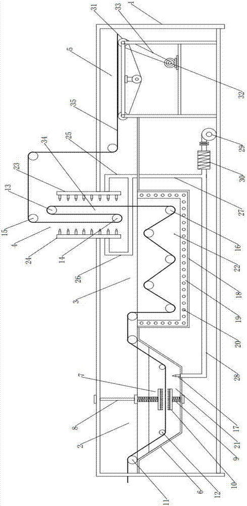
Chain cleaning and oiling equipment
A technology for chain cleaning and equipment, applied in cleaning methods and utensils, cleaning methods using tools, cleaning methods using liquids, etc. The effect of polluting the environment and improving the cleaning effect
- Summary
- Abstract
- Description
- Claims
- Application Information
AI Technical Summary
Problems solved by technology
Method used
Image

Examples
Embodiment Construction
[0022] First of all, it should be noted that the specific structure, features and advantages of the chain cleaning and oiling equipment of the present invention will be specifically described below by way of example, but all descriptions are only for illustration and should not be understood No limitation of the invention is intended. In addition, any single technical feature described or implied in each embodiment mentioned herein, or any single technical feature shown or implied in each drawing, can still be described in these technical features (or their equivalents) ) to continue any combination or deletion, so as to obtain more other embodiments of the present invention that may not be directly mentioned herein. In addition, for the sake of simplifying the drawings, the same or similar technical features may only be marked in one place in the same drawing.
[0023] In the description of the present invention, it should be noted that the orientation or positional relation...
PUM
 Abstract
Description
Claims
Application Information
 - R&D Engineer
- R&D Manager
- IP Professional
- Industry Leading Data Capabilities
- Powerful AI technology
- Patent DNA Extraction
Browse by: Latest US Patents, China's latest patents, Technical Efficacy Thesaurus, Application Domain, Technology Topic, Popular Technical Reports.
© 2024 PatSnap. All rights reserved.Legal|Privacy policy|Modern Slavery Act Transparency Statement|Sitemap|About US| Contact US: help@patsnap.com