
Split type bearing seat used for anti-rolling device

A split-type, anti-rolling technology, applied in the direction of bearing components, shafts and bearings, rigid supports of bearing components, etc., can solve the problems of inapplicability, large installation space, and inability to prevent rollover, etc., to achieve stable structure and effective maintenance. Convenience, anti-rolling effect

Inactive Publication Date: 2017-07-07
响水县翔宇传动件有限公司
View PDF1 Cites 1 Cited by
  • Summary
  • Abstract
  • Description
  • Claims
  • Application Information

AI Technical Summary

Problems solved by technology

[0002] The bearing seat device is widely used in various mechanical equipment. The bearing seat of the existing bearing seat device is an integral type, which is mainly installed at the two ends of the torsion bar. The top of the bearing seat is fixedly connected with the bogie. During the installation process, it is necessary to Put the torsion bar shaft on the bearing seat first, and then install the bearing seat and the torsion bar shaft on the vehicle bogie. In the case of the frame, the existing integral bearing seat cannot be applied, and the current existing bearing seat is difficult to achieve anti-rolling, which is extremely inconvenient, especially the anti-rolling stiffness of the vehicle is very high, and the anti-rolling device passes The anti-torque provided by the torsion bar reduces the roll angle of the vehicle, but many bearing housings cannot prevent roll, so people's requirements cannot be fulfilled

Method used


Image

  • Split type bearing seat used for anti-rolling device
  • Split type bearing seat used for anti-rolling device
  • Split type bearing seat used for anti-rolling device

Examples


Embodiment Construction

[0014] The following will clearly and completely describe the technical solutions in the embodiments of the present invention with reference to the accompanying drawings in the embodiments of the present invention. Obviously, the described embodiments are only some, not all, embodiments of the present invention. Based on the embodiments of the present invention, all other embodiments obtained by persons of ordinary skill in the art without making creative efforts belong to the protection scope of the present invention.

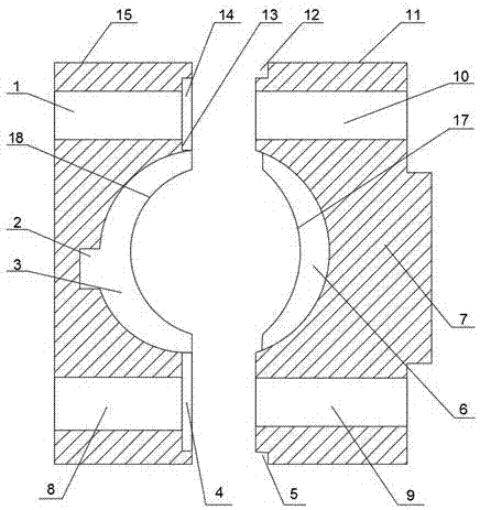
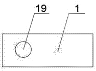
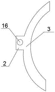
[0015] see Figure 1-3 , the present invention provides a technical solution: a split bearing housing for an anti-rolling device, including a front bearing housing 11 and a rear bearing housing 15, the rear bearing housing 15 is provided with bolts A1 and bolts B8 inside, and the rear bearing housing 15 is provided with a left half-bearing cavity 3, and the left half-bearing cavity 3 is provided with a left rib 18, and the left half-bearing cavity 3 is provide...


PUM


Abstract

The invention discloses a split type bearing seat used for an anti-rolling device. The split type bearing seat used for the anti-rolling device comprises a front bearing seat body and a rear bearing seat body. A bolt A and a bolt B are arranged in the rear bearing seat body. A left half bearing cavity is formed in the rear bearing seat body. A left blocking edge is arranged on the left half bearing cavity. A bearing limiting device is arranged on the left half bearing cavity. A bearing limiting hole is formed in the bearing limiting device. An upper convex edge is arranged on the right side of the bolt A. A lower convex edge is arranged on the right side of the bolt B. A joint face is arranged on the left side of the upper convex edge. A bolt C and a bolt D are arranged in the front bearing seat body. A right half bearing seat cavity is formed in the front bearing seat body. A right blocking edge is arranged on the right half bearing seat cavity. An external mounting table is arranged inside the front bearing seat body. An upper groove is formed in the upper portion of the front bearing seat body, a lower groove is formed in the lower portion of the front bearing seat body, the upper groove and the lower groove are formed in the upper side and the lower side of the front bearing seat body, and the size of the upper groove is equal to the size of the lower groove. The split type bearing seat used for the anti-rolling device can effectively prevent rolling, is stable in structure and can bring convenience for maintenance.

Description

technical field [0001] The invention relates to the field of bearing device components, in particular to a split bearing seat used for an anti-rolling device. Background technique [0002] The bearing seat device is widely used in various mechanical equipment. The bearing seat of the existing bearing seat device is an integral type, which is mainly installed at the two ends of the torsion bar. The top of the bearing seat is fixedly connected with the bogie. During the installation process, it is necessary to Put the torsion bar shaft on the bearing seat first, and then install the bearing seat and the torsion bar shaft on the vehicle bogie. In the case of the frame, the existing integral bearing seat cannot be applied, and the current existing bearing seat is difficult to achieve anti-rolling, which is extremely inconvenient, especially the anti-rolling stiffness of the vehicle is very high, and the anti-rolling device passes The anti-torque provided by the torsion bar redu...

Claims


Application Information

Patent Timeline
Patent Type & Authority Applications(China)
IPC IPC(8): F16C35/00
CPCF16C35/00
Inventor 董郁春
Owner 响水县翔宇传动件有限公司
Learn More