Shadow imaging system for multi-spraying-hole spraying measurement

A technology of shadow imaging and orifice, applied in the field of visual measurement

Inactive Publication Date: 2017-07-07
HARBIN ENG UNIV
View PDF2 Cites 19 Cited by
  • Summary
  • Abstract
  • Description
  • Claims
  • Application Information

AI Technical Summary

Problems solved by technology

[0005] The purpose of the present invention is to propose a shadow method imaging system for measuring multi-nozzle spray in view of the disadvantage that the existing shadow imaging system for spray measurement can only observe single-hole spray

Method used


Image

  • Shadow imaging system for multi-spraying-hole spraying measurement

Examples


Embodiment Construction

[0015] It should be noted that, in the case of no conflict, the embodiments in the present application and the features in the embodiments can be combined arbitrarily with each other. The present invention will be described in detail below with reference to the accompanying drawings and examples.

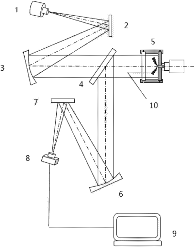
[0016] The invention provides a shadow imaging system for multi-nozzle spray measurement, which includes a light source arranged along the optical path, a first plane mirror, a collimating mirror, a half mirror, a combustion chamber, a focusing mirror, a second plane mirror, a high-speed Photo camera and computer. Wherein, the half mirror is located between the collimating mirror and the combustion chamber, and between the combustion chamber and the focusing mirror.

[0017] The light from the light source shines on the first plane mirror, is reflected by the plane mirror and then shines on the collimating reflector. After passing through the collimating reflector, it becomes paral...


PUM


Abstract

The invention belongs to the field of visualized measurement based on shadow-method imaging and in particular relates to a shadow imaging system for multi-spraying-hole spraying measurement. According to the shadow imaging system for the multi-spraying-hole spraying measurement, light penetrates through a semi-reflecting and semi-transmitting mirror and is irradiated into a combustion chamber; the light is reflected by the semi-reflecting and semi-transmitting mirror and is irradiated to a focusing mirror in a direction vertical to an original direction; the light is gathered through the focusing mirror and is reflected through a second plane mirror and then finally enters a high-speed photographic camera; an image file is stored in a computer. A multi-spraying-hole oil spraying device is mounted on a wall surface at the opposite side of a visualized window and mirror-surface treatment is carried out on the wall surface, which is provided with the oil spraying device, of the combustion chamber; direction selectivity of light transmission of the semi-reflecting and semi-transmitting mirror is combined and the semi-reflecting and semi-transmitting mirror is placed in a manner of forming an angle of 45 degrees with a horizontal direction, so that a plurality of beams of sprayed mist, which are sprayed by the oil spraying device, are observed from a front surface, and furthermore, the shadow imaging system can be applied to the multi-spraying-hole oil spraying device and the aim of observing multi-spraying-hole oil spraying at the same time is realized.

Description

technical field [0001] The invention belongs to the field of visualization measurement based on shadow method imaging, in particular to a shadow imaging system for multi-nozzle spray measurement. Background technique [0002] The characteristics of diesel engine spray have an important impact on the economy and emissions of diesel engines, so the research on diesel engine spray is a very active field in the research of diesel engine combustion. As a traditional optical test method for spray penetration and spray cone angle, the existing shadow test system has two common optical path arrangements: reflective and transmissive. In the transmissive optical path system, the light source, lens, combustion chamber, and high-speed camera are on the same straight line, and the light emitted from the light source becomes parallel light after passing through the collimating lens, passes through the measured flow field, and then enters through the focusing lens. High speed camera. In ...

Claims


Application Information

Patent Timeline
Patent Type & Authority Applications(China)
IPC IPC(8): G01N21/85G01N21/01G03B39/00
CPCG03B39/00G01N21/01G01N21/85
Inventor 刘龙彭雁韩长福袁志国马修真
Owner HARBIN ENG UNIV
Why Eureka
Try Eureka