Optical filter and display evaluation system

An optical filter and waveform technology, applied in the direction of optical instrument testing, optics, optical components, etc., to achieve accurate display evaluation, suppress the generation of ripple patterns, and suppress the effects of ripple patterns

Active Publication Date: 2012-05-16
IIX
View PDF10 Cites 9 Cited by
  • Summary
  • Abstract
  • Description
  • Claims
  • Application Information

AI Technical Summary

Problems solved by technology

[0003] However, when an object having a periodic pattern is captured by a camera using v...

Method used


Image

  • Optical filter and display evaluation system
  • Optical filter and display evaluation system
  • Optical filter and display evaluation system

Examples


no. 1 approach

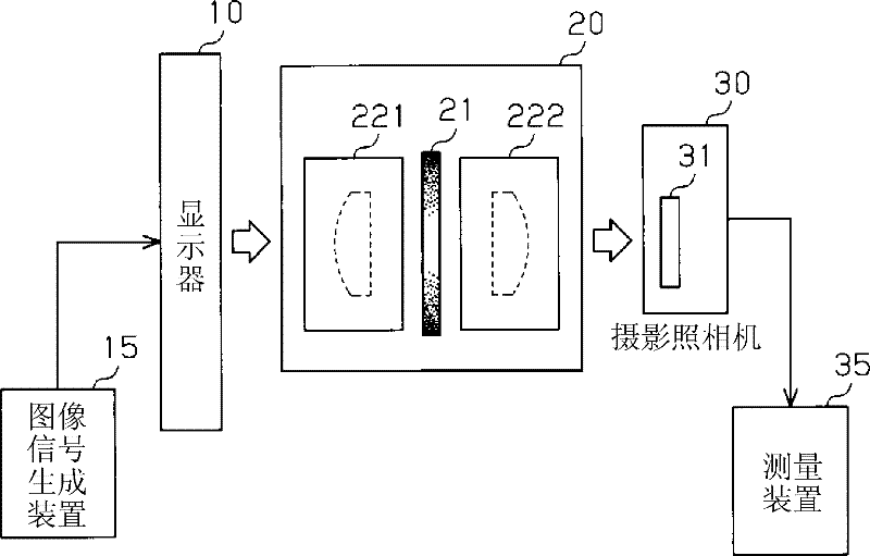
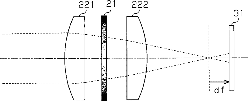
[0053] Next, the optical filter and display evaluation system of the present invention will be described. In this embodiment, it is assumed that a CCD image sensor is used to evaluate the image quality of a display panel to be adjusted. Here, if figure 1 As shown, a liquid crystal panel 10 is used as a display panel to be adjusted. The liquid crystal panel 10 forms an image by pixel elements arranged at a predetermined period (first pitch).

[0054] Furthermore, a display evaluation system for evaluating the liquid crystal panel 10 is composed of an optical adjustment device 20 , a photographing camera 30 , and a measurement device 35 . In addition, an image signal generating device 15 is connected to the liquid crystal panel 10 .

[0055] Here, a photographing camera 30 serving as an imaging unit (imaging device) captures an image acquired via the optical adjustment device 20 , and supplies output image data to the measuring device 35 . In this embodiment, a monochrome ca...

no. 2 approach

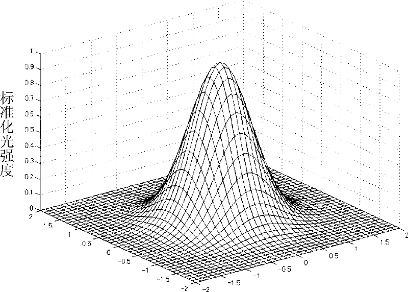
[0081] In the first embodiment described above, the transmittance distribution is provided to the optical filter 21 by providing the apertures 211 in the optical filter 21 so that the distribution density thereof changes concentrically. In the second embodiment, an optical filter using apertures having normally distributed aperture widths will be described.

[0082] here, yes Figure 8 The pixel 11 of the liquid crystal panel 10 shown in (a) uses Figure 8 The optical filter 21 shown in (b). This optical filter 21 has an opening 213 . The opening 213 is constituted by an edge of a shape obtained by joining two normal distribution curves arranged symmetrically with respect to the transverse axis 214 . In this embodiment, the transverse axis 214 is arranged so as to pass through the center of the optical axis (optical filter 21 ).

[0083] In the case of using this optical filter 21, the transverse axis 214 and the direction in which the pixels 11 of RGB colors are arranged ...


PUM


Abstract

A display evaluation system for evaluating a liquid crystal panel (10) comprises an optical adjustment unit (20), a photographic camera (30), and a measurement unit (35). An image signal generation unit (15) is connected to the liquid crystal panel (10). The photographic camera (30) is provided with a CCD image sensor (31). The optical adjustment unit (20) is comprised of lenses (221, 222). In the optical adjustment unit (20), an optical filter (21) which has a transmittance gradient provided by machining a metal plate into a mesh structure is arranged in a position of a diaphragm. The CCD image sensor (31) arranged in a defocus position is shaped to suppress a response beyond the Nyquist frequency. Consequently, it is possible to reduce the occurrence of a moire pattern and to capture an image resolved for each pixel.

Description

technical field [0001] The present invention relates to an optical filter and a display evaluation system used when evaluating the image quality of a display. Background technique [0002] Currently, production lines for displays such as liquid crystal panels are constructed so that uniform quality can be realized. However, in such a production line, manufacturing variations also occur among individual displays. Therefore, various studies have been made to adjust displays that output better images (for example, refer to Patent Document 1). In the technology described in this patent document 1, the image quality of the adjustment target device is adjusted so that it approximates the image quality of the target device. [0003] However, when an object having a periodic pattern is photographed by a camera using various imaging devices, moire patterns may appear in the photographed image, but such moire patterns do not actually appear on the screen. . The moiré pattern is a ...

Claims


Application Information

Patent Timeline
IPC IPC(8): G02B27/46G01M11/00G02B5/00G03B11/00H04N5/225
CPCH04N5/2176H04N17/002G02B27/46G03B11/00H04N25/63G01M11/00G02B5/00
Inventor 坂本隆田畑真哉太田明男村濑浩
Owner IIX
Why Eureka
Try Eureka