
Non-reversible cirucit device, non-reversible cirucit and communication device

A circuit device and circuit technology, applied in the direction of circuits, electrical components, waveguide devices, etc., can solve the problems of reduced inductance, reduced attenuation of the second and third harmonic components of the fundamental wave, and difficulty in manufacturing. Small size, effect of suppressing frequency components

Inactive Publication Date: 2004-08-04
MURATA MFG CO LTD
View PDF1 Cites 0 Cited by
  • Summary
  • Abstract
  • Description
  • Claims
  • Application Information

AI Technical Summary

Problems solved by technology

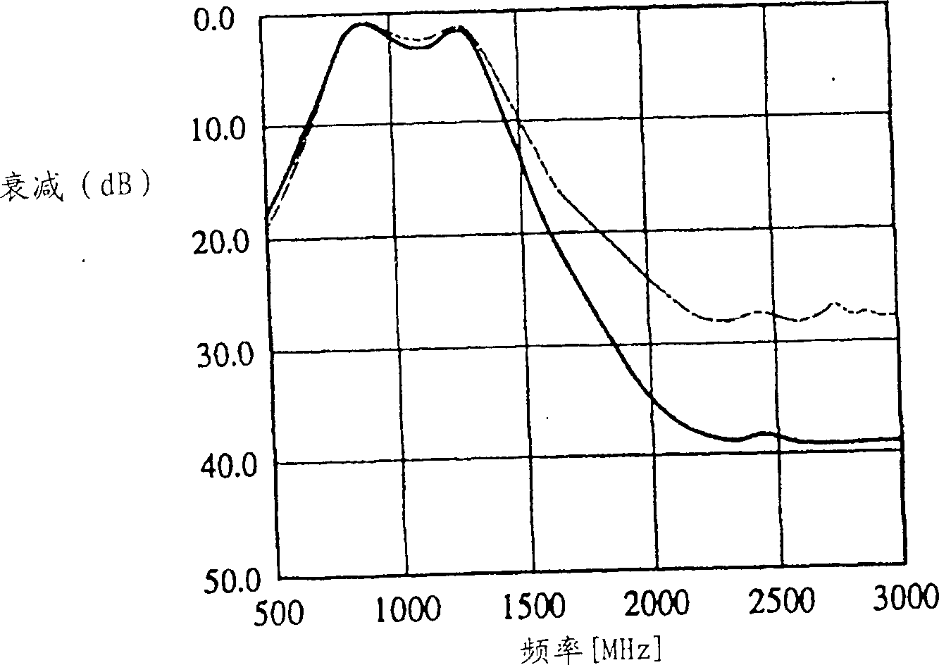
However, if the size of the solenoid-shaped inductor is reduced, its inductance will also be reduced, and the attenuation of the second and third harmonic components of the fundamental wave will also be reduced.
To reduce the size of a solenoidal inductor without reducing its inductance, the magnetic elements in the resulting solenoidal structure should be properly designed; however, the problem with the newly required magnetic elements in this structure is It is not easy to manufacture, and the cost increases

Method used


Image

  • Non-reversible cirucit device, non-reversible cirucit and communication device
  • Non-reversible cirucit device, non-reversible cirucit and communication device
  • Non-reversible cirucit device, non-reversible cirucit and communication device

Examples


Embodiment Construction

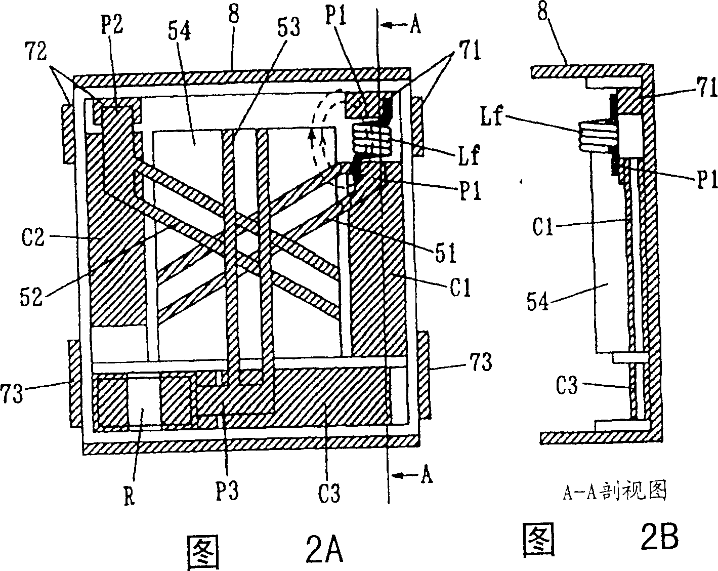
[0037] See below Figure 1 to 3 The structure of the isolator according to the first embodiment will be described. figure 1 It is an expanded perspective view of the isolator; FIG. 2A is its top view, and FIG. 2B is a cross-sectional view along the line A-A in FIG. 2A.

[0038] Such as figure 1 As shown in 2B, in the isolator, the disk-shaped permanent magnet 3 is placed on the inner surface of the top yoke box 2 made of magnetic material, such as figure 1 As shown in and 2, the top yoke box 2 and the substantially U-shaped bottom yoke 8 made of the same material constitute a closed magnetic circuit. The resin case 7 is placed on the bottom surface of the bottom yoke 8, and the magnetic assembly 5 , The matching circuits C1, C2 and C3, the terminal resistance R and the inductance Lf are placed in the tree finger housing 7.

[0039] In the magnetic component 5, the common ground portion of the three central conductors 51, 52, and 53 of the same shape as the bottom surface of the ...


PUM


Abstract

To provide a nonreciprocal circuit device which is compact and capable of obtaining a large attenuation in a specified frequency band without increasing the cost, and provided with at least a built-in inductor for a filter, a nonreciprocal circuit constituted together with the nonreciprocal circuit device, and a communication device using the circuit, central conductors are disposed in a ferrite to which the DC magnetic field is applied in an intersecting manner with each other, matching capacitors are respectively connected between port sections of the central conductors and a ground to constitute a nonreciprocal circuit, a solenoid-shaped inductor is connected between the port section of the central conductor and a signal input / output terminal, and the inductor is disposed in a relationship so that the direction of the magnetic flux which is generated by this inductor and passes through the ferrite is substantially perpendicular to the direction of the DC magnetic field to the ferrite.

Description

Technical field [0001] The present invention relates to a non-reciprocal circuit device, for example, a non-reciprocal circuit composed of an isolator and a circulator used in a high-frequency band including a microwave band and a non-reciprocal circuit, and a communication device using these components. Background technique [0002] So far, non-reciprocal circuit devices, such as lumped constant isolators and lumped constant circulators used in communication devices, have characteristic advantages in that the signal attenuation in the transmission direction is extremely small, and the attenuation in the opposite direction is extremely large. [0003] Figure 7 It is an exploded view of an existing isolator, and Figures 8A and 8B are a top view and a cross-sectional view of its internal structure, respectively. Figure 9 is an equivalent circuit diagram. [0004] Such as Figure 7 , 8A and 8B, the isolator, including the central conductor 51, 52 and 53 and the ferrite 54 of the m...

Claims


Application Information

Patent Timeline
IPC IPC(8): H01P1/36H01P1/32H01P1/383H01P1/387
CPCH01P1/387H01P1/32
Inventor 长谷川隆
Owner MURATA MFG CO LTD
Learn More