
Conductive parts

A technology of conductive components and conductivity, applied in the direction of printed circuit components, conductive materials, conductive materials, etc.

Inactive Publication Date: 2008-08-27
NXP BV
View PDF3 Cites 0 Cited by
  • Summary
  • Abstract
  • Description
  • Claims
  • Application Information

AI Technical Summary

Problems solved by technology

However, in recent years, it is necessary to effectively attenuate noise of several GHz order due to an increase in the clock frequency of electronic equipment such as PC (Personal Computer), whereby it is difficult to effectively attenuate noise of several GHz or higher order by the FTC described above

Method used


Image

  • Conductive parts
  • Conductive parts
  • Conductive parts

Examples


Embodiment Construction

[0024] The invention is described next with reference to the following figures.

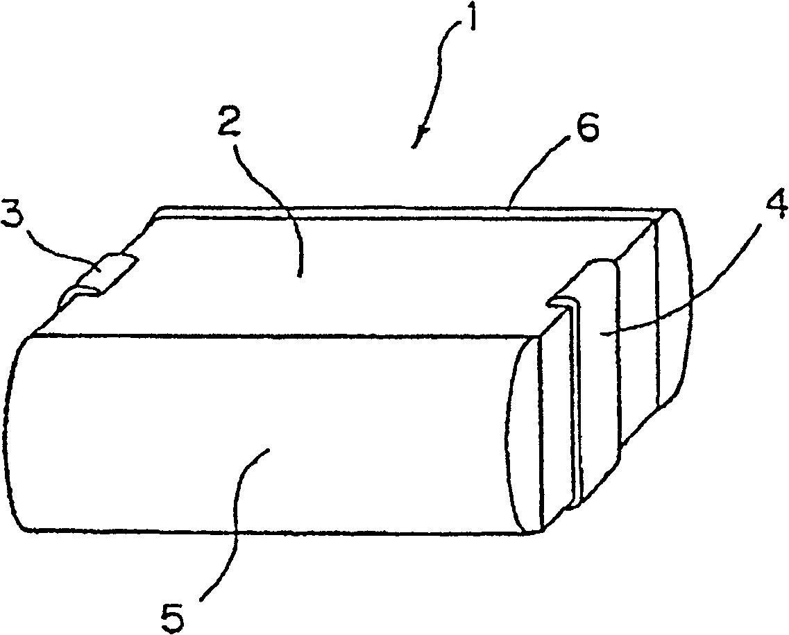
[0025] figure 1 is a signal line (refer to later described figure 2 ) perspective view of the EMI filter.

[0026] The EMI filter 1 is provided with a rectangular planar hexagonal shaped ceramic base 2 mainly composed of ceramics. The input external electrode 3 and the output external electrode 4 are formed on the center positions of the right and left surfaces of the ceramic base 2 . In addition, ground external electrodes 5 and 6 are formed on the front and rear surfaces of the ceramic base 2 .

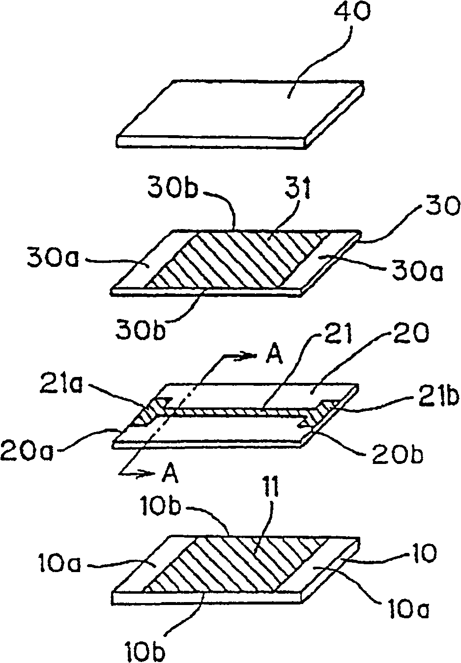
[0027] figure 2 yes figure 1 An exploded perspective view of the ceramic base body of the shown EMI filter, which is divided into four layers.

[0028] Each of the four ceramic layers 10, 20, 30 and 40 is formed by laminating a plurality of sheets consisting essentially of ceramic.

[0029] A square-shaped ground electrode 11 is formed on a surface of the bottommost ceramic layer 10 of these f...


PUM


Abstract

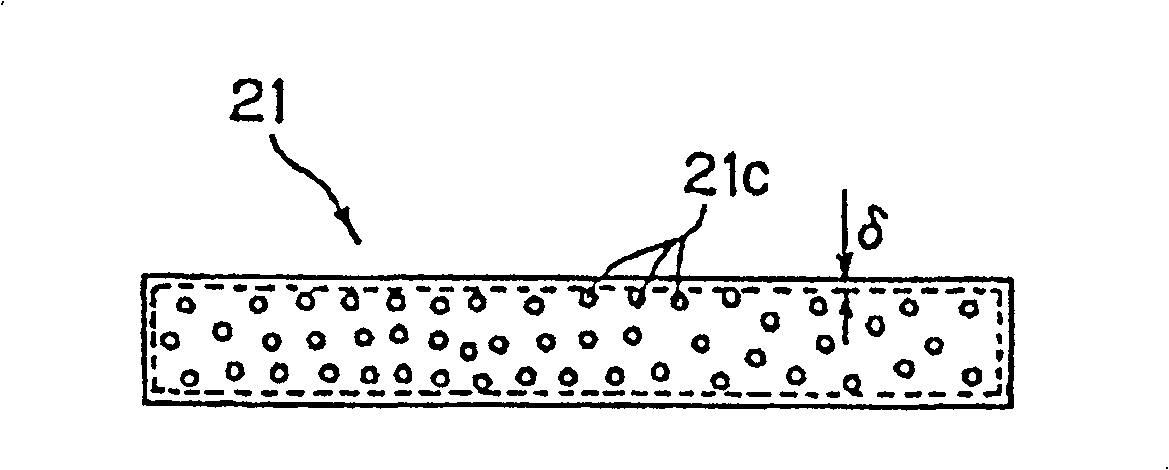
The object of the invention is to provide a conductive member capable of attenuating the noise having frequency components, for example, of the order of several GHz efficiently. Signal line (21) is formed by using the first conductive paste containing a silver powder, a ferrite powder, an organic binder, a dispersant, and a solvent.

Description

technical field [0001] The invention relates to an electrically conductive component comprising a first and a second material. Background technique [0002] Hitherto, in order to eliminate high-frequency noise mixed in electronic circuits such as FTC (bypass capacitor) is used. [0003] When a signal is input to the above FTC, DC and low frequency components of the input signal are hardly attenuated while the high frequency component of the input signal is greatly attenuated. However, FTC shows a frequency characteristic in which although the amount of attenuation of the signal increases as the frequency of the input signal becomes higher, on the contrary, now, the amount of attenuation decreases as the frequency of the input signal rises. Therefore, even if the characteristic of reducing the amount of attenuation is displayed, high-frequency noise can be eliminated by FTC when the frequency is not extremely high. However, it is necessary to effectively attenuate noise of ...

Claims


Application Information

Patent Timeline
IPC IPC(8): H03H1/00H01B1/00H05K1/02
CPCH03H1/0007H01F1/37H05K1/0233H05K9/00
Inventor K·霍里H·伊施达
Owner NXP BV
Learn More