Intelligent connecting cabinet lock

A transfer cabinet and cabinet technology, applied in building locks, lock applications, electric locks, etc., can solve the problems of high cost, large management loopholes, easy duplication, etc., to achieve the elimination of responsibility pressure, systematic management, and easy management Effect

Active Publication Date: 2017-07-11
ZHONGSHAN ROYALWAND HARDWARE
View PDF6 Cites 6 Cited by
  • Summary
  • Abstract
  • Description
  • Claims
  • Application Information

AI Technical Summary

Problems solved by technology

[0004] With the continuous improvement of life, most of the locks widely used in the market are mechanical keys, and mechanical key locks will bring most inconvenience to users, such as high mutual opening rate (one key can open several locks) ; Easy to copy (as long as someone who has used it may copy the key privately, the management loopholes are large); and the management cost in its use is also very high, such as: a large number of keys, difficult management, and high cost; after using the key It still needs to be returned, and the labor and transportation costs are high; the scene is stolen or damaged, and the status of the cabinet cannot be found and understood in time
[0005] Moreover, there are two types of cabinet doors and cabinet walls: left-opening (cabinet door on the left, cabinet wall on the right) and right-opening (cabinet door on the right, cabinet wall on the left) according to different application scenarios. The locks for transfer cabinets are generally divided into two types: left-opening structure and right-opening structure, and the locks for the transfer cabinet with the left-opening door structure are difficult to apply to the transfer cabinet with the right-opening door, and the locks for the transfer cabinet with the right-opening door structure are difficult to apply to the left. The transfer cabinet with the door opening method has poor versatility

Method used


Image

  • Intelligent connecting cabinet lock
  • Intelligent connecting cabinet lock
  • Intelligent connecting cabinet lock

Examples


Embodiment Construction

[0040] The present invention will be further described below in conjunction with accompanying drawing:

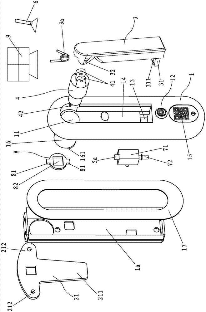
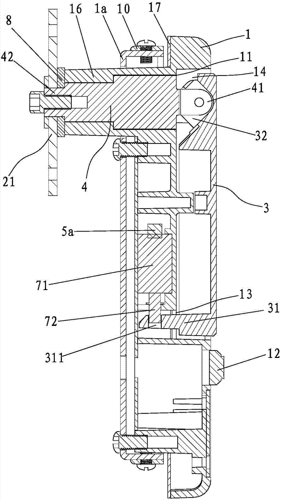
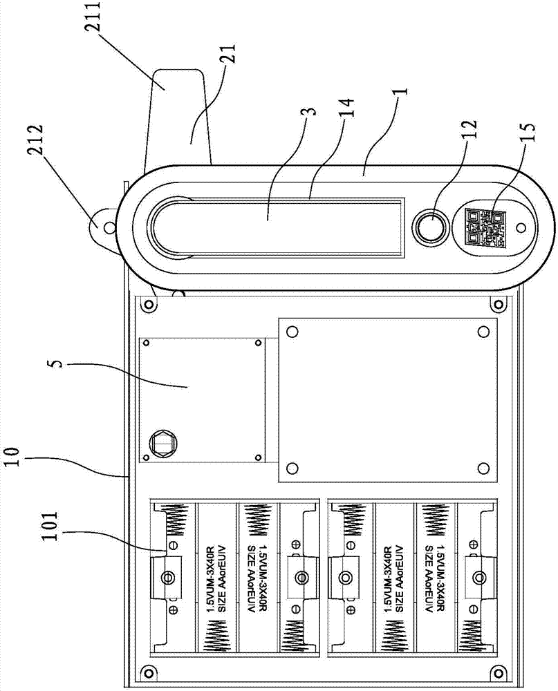
[0041] Such as Figure 1 to Figure 7 The shown lock for an intelligent transfer cabinet includes a circuit board 5, a mounting base 1 fixed to the cabinet door, a main locking plate 21 inside the cabinet, and a handle 3 outside the cabinet. The mounting base 1 There is a rotating shaft hole 11 connecting the inside and outside of the cabinet. The rotating shaft hole 11 is pierced with a shaft that can rotate in the rotating shaft hole 11 and is used to connect the main locking plate 21 and the handle 3 so that the main locking plate 21 and the handle 3 are coaxial together. The rotating shaft 4, the main locking plate 21 is provided with a locking boss 211 that can be stuck on the door frame when rotating so as to lock the cabinet door, and the mounting base 1 is provided with the locking boss 211 to lock the cabinet door. The locking structure that can limit the rotation ...


PUM


Abstract

The invention discloses an intelligent connecting cabinet lock. The intelligent connecting cabinet lock comprises a main circuit board, a mounting base fixed to a cabinet door, a main locking plate and a handle, wherein the main locking plate is arranged in a cabinet, the handle is arranged on the outer side of the cabinet, a rotating shaft hole communicating with the interior and the exterior of the cabinet is formed in the mounting base, a rotating shaft which is connected with the main locking plate and the handle to enable the main locking plate and the handle to rotate coaxially is arranged in the rotating shaft hole in a penetrating mode, the main locking plate is provided with a locking boss which can be clamped on a door frame during rotation so as to lock the cabinet door, the mounting base is provided with a locking structure capable of limiting the rotation of the handle when the locking boss locks the cabinet door, the locking structure is electrically connected with the main circuit board, an antenna is further electrically connected to the main circuit board, the main circuit board can receive signals sent by a remote control system through the antenna so as to control unlocking and locking of the locking structure, and the mounting base is provided with an exposed key switch which is electrically connected with the main circuit board and can send signals to the remote control system when pressed.

Description

[0001] 【Technical field】 [0002] The invention relates to an intelligent transfer cabinet lock. [0003] 【Background technique】 [0004] With the continuous improvement of life, most of the locks widely used in the market are mechanical keys, and mechanical key locks will bring most inconvenience to users, such as high mutual opening rate (one key can open several locks) ; Easy to copy (as long as someone who has used it may copy the key privately, the management loopholes are large); and the management cost in its use is also very high, such as: a large number of keys, difficult management, and high cost; after using the key It still needs to be returned, and the labor and transportation costs are high; if it is stolen or damaged on site, it is impossible to find and understand the status of the cabinet in time. [0005] Moreover, there are two types of cabinet doors and cabinet walls: left-opening (cabinet door on the left, cabinet wall on the right) and right-opening (cabi...

Claims


Application Information

Patent Timeline
Patent Type & Authority Applications(China)
IPC IPC(8): E05B65/52E05B49/00
CPCE05B49/00E05B65/52
Inventor 谢若鹏陈梅芳魏厚军
Owner ZHONGSHAN ROYALWAND HARDWARE
Why Eureka
Try Eureka