Plane two-freedom-degree parallel mechanism containing coupled branch chain

A degree of freedom, plane technology, applied in manipulators, program-controlled manipulators, manufacturing tools, etc., can solve the problems of affecting the motion accuracy of the mechanism, increase the manufacturing and assembly costs, etc., and achieve large motion space, less passive motion joints, and good economy. Effect

Active Publication Date: 2017-07-14
锐依德(上海)机器人科技有限公司
View PDF6 Cites 4 Cited by
  • Summary
  • Abstract
  • Description
  • Claims
  • Application Information

AI Technical Summary

Problems solved by technology

The number of joints of a parallel mechanism is usually greater than the number of degrees of freedom of the mechanism, which leads to many passive joints in the mechanism, which increases the cost of manufacturing and assembly, and even affects the motion accuracy of the mechanism

Method used


Image

  • Plane two-freedom-degree parallel mechanism containing coupled branch chain
  • Plane two-freedom-degree parallel mechanism containing coupled branch chain
  • Plane two-freedom-degree parallel mechanism containing coupled branch chain

Examples


Embodiment 1

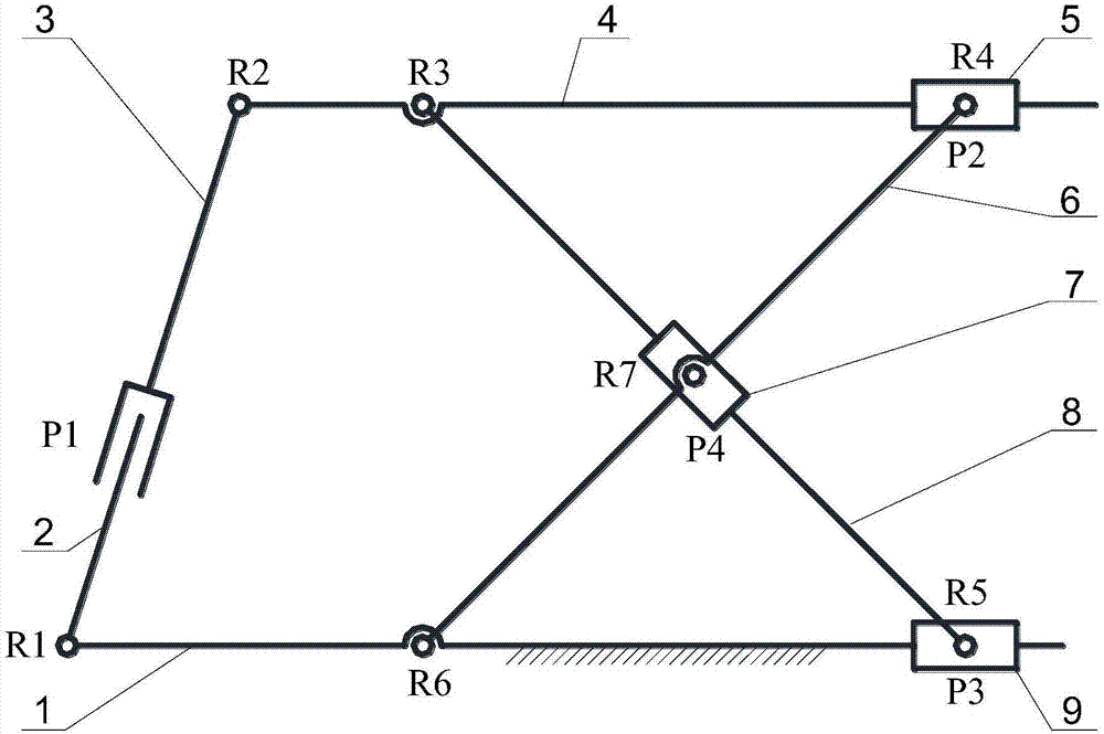
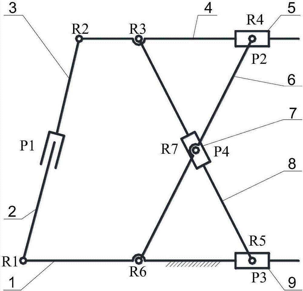
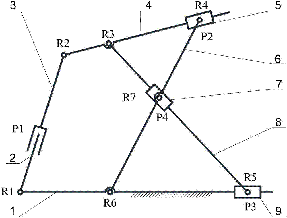
[0015] exist Figure 1-3 In the schematic diagram of the planar two-degree-of-freedom parallel mechanism with coupling branches shown, the first connecting rod 1 is a fixed connecting rod, the fourth connecting rod 4 is an end effector, and one end of the first connecting rod connects with the second One end of the connecting rod 2 is connected, the other end of the first connecting rod 1 is provided with a first slide block 9 to form a moving pair P3, the other end of the second connecting rod is connected with one end of the third connecting rod 3 through a moving pair P1, and the third The other end of the connecting rod is connected to one end of the fourth connecting rod 4 through the rotating pair R2, the other end of the fourth connecting rod is provided with a second slider 5 to form a moving pair P2, and one end of the fifth connecting rod 6 is connected to the fourth connecting rod through the rotating pair R4. The second slider is connected, the other end of the fif...

Embodiment 2

[0024] The central portion of the fifth connecting rod is provided with a third slider 7 to form a moving pair P4, and the central portion of the sixth connecting rod is connected to the third sliding block through a rotating pair R7; other components and connections are the same as those in Embodiment 1.

[0025] The embodiment of the present invention can also be used to carry goods, and the loading platform or the loading box is arranged on the fourth connecting rod 4 to realize the transfer and dumping of the goods.

[0026] It can be seen that the present invention can select any two sliders as input, and according to the difference of the selected input sliders and the direction of the input motion, a variety of different motion trajectories and motion results can be obtained, which can meet the needs of various occasions , this mechanism can be widely promoted and applied.

[0027] In order to increase the stability and rigidity of the fixed link, multiple planar two-de...


PUM


Abstract

The invention discloses a plane two-freedom-degree parallel mechanism containing a coupled branch chain. The mechanism comprises six connecting rods and three sliding blocks; the first connecting rod is a fixed connecting rod, the fourth connecting rod is a tail end executor, one end of the first connecting rod is connected with one end of the second connecting rod, the other end of the first connecting rod is provided with a first sliding block, the other end of the second connecting rod is connected with one end of the third connecting rod, the other end of the third connecting rod is connected with one end of the fourth connecting rod, the other end of the fourth connecting rod is provided with a second sliding block, one end of the fifth connecting rod is connected with the second sliding block, the other end of the fifth connecting rod is connected with the middle of the first connecting rod, one end of the sixth connecting rod is connected with the middle of the fourth connecting rod, the other end of the sixth connecting rod is connected with the first sliding block, a third sliding block is arranged at the central position of the fifth connecting rod or the sixth connecting rod, and the middle of the fifth connecting rod or the sixth connecting rod is connected with the third sliding block. Different moving pairs can be selected as moving input, lifting and tipping motions of the tail end executor can be achieved, and the application range is wide.

Description

technical field [0001] The invention relates to the field of planar mechanisms, in particular to a parallel mechanism. Background technique [0002] Parallel mechanisms are generally composed of multiple kinematic branches. Compared with series mechanisms, they have been widely used in many fields of modern technology because of their advantages such as low inertia, high stiffness, and strong load capacity. The number of joints of a parallel mechanism is usually greater than the number of degrees of freedom of the mechanism, which leads to many passive joints in the mechanism, which increases the cost of manufacturing and assembly, and even affects the motion accuracy of the mechanism. The planar two-degree-of-freedom parallel machine mechanism is the parallel mechanism with the least degree of freedom, and it has the advantages of simple structure, easy control, and good economy, making planar parallel robots widely used in machinery manufacturing, construction, food, e-com...

Claims


Application Information

Patent Timeline
Patent Type & Authority Applications(China)
IPC IPC(8): B25J9/00
CPCB25J9/0072
Inventor 史小华葛晨优朱家增廖梓宇林赛
Owner 锐依德(上海)机器人科技有限公司
Why Eureka
Try Eureka