Water closet vertical-pouring molding structure capable of simplifying production process

A technology of forming structure and production process, applied in ceramic forming machines, manufacturing tools, molds, etc., can solve the problems of time-consuming and laborious operation of live blocks in the pot, complicated process operations, and easy breakage of live blocks, and improve the problem of poor glazing. Hidden dangers, improving enterprise efficiency, and the effect of no hygienic dead ends

Pending Publication Date: 2017-07-14
HUIDA SANITARY WARE
View PDF3 Cites 4 Cited by
  • Summary
  • Abstract
  • Description
  • Claims
  • Application Information

AI Technical Summary

Problems solved by technology

Molding workers need to control the distance and angle of each eye hole when punching holes. The technical requirements are strict, and the process operation is complicated and time-consuming.
[0004] Although the structure without hydrosphere has been adjusted on the basis of ordinary hydrosphere, most of the brushing holes have been canceled, and the molding operation process has been simplified during the molding stage, but there is still a water retaining edge on the upper part of the diversion platform. With the existence of the water edge, the operation of the loose block in the pot is time-consuming and laborious, and the problem that the live block is easily damaged still exists
[0005] With the continuous development and progress of the sanitary ceramics industry, the above two molding structures are difficult to meet the development of production, and a new molding structure needs to be developed to improve the current status quo

Method used


Image

  • Water closet vertical-pouring molding structure capable of simplifying production process
  • Water closet vertical-pouring molding structure capable of simplifying production process
  • Water closet vertical-pouring molding structure capable of simplifying production process

Examples


Embodiment Construction

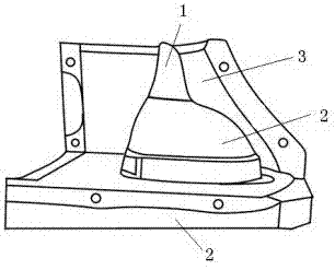
[0019] As shown in the figure, the movable block of the pot internal water area model includes the water seal water storage area active block 1, the circle plate model 2, and the big gang model 3.

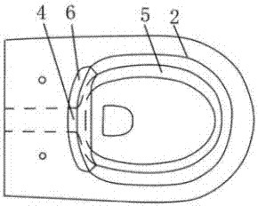
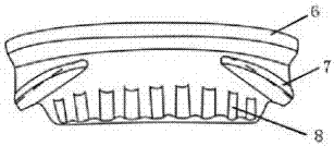
[0020] The figure shows that the water inlet of the toilet circle of the ring plate model 2 cancels the single-sided slurry suction channel and replaces it with a double-sided slurry suction channel 4, and the structure of the double-sided slurry suction channel 4 transitions to both sides and is in phase with the diversion platform 5 Connect, cancel the water retaining edge on the guide platform 5 tops.

[0021] Due to the removal of the water retaining edge, the ring plate model 2 has become an integral structure. If the product is larger, the ring plate model 2 can be changed into one large and one small two loose blocks, which is easy to operate. Due to the cancellation of the water retaining edge, the hidden danger of poor glazing at the lower part of the water retaining edge ...


PUM


Abstract

The invention discloses a water closet vertical-pouring molding structure capable of simplifying a production process and belongs to the technical field of water closet pouring molding models. The structure is used for water closet vertical-pouring molding. According to the technical scheme, a paste sucking channel at a water closet girth water inlet of a girth plate model is a double-face paste sucking channel; the double-face paste sucking channel extends to the two sides to be connected with a guide platform; the upper portion of the guide platform is provided with a smooth plane; a sticky plate is bound to the front portion of the double-face paste sucking channel; and guide bars and water distribution grooves are designed in the inner side of the sticky plate. The girth plate model is of an integrated structure, and operation is facilitated; since a water stopping edge is omitted, the potential problem of poor glazing of the lower portion of the water stopping edge during production and glazing is effectively relieved, and meanwhile, cleaning is more convenient and sanitary dean angles are absent during daily use by a customer; and the lower portion of the sticky plate is open, no residual water exists after flushing, and water stains accumulated in a long term are avoided. By adoption of the water closet vertical-pouring molding structure, the production process can be simplified, operation is easy and convenient, the labor intensity of workers is relieved, the efficiency is improved, and enterprise benefits are increased.

Description

technical field [0001] The invention relates to a vertical pouring molding structure of a toilet, belonging to the technical field of toilet casting molding models. Background technique [0002] At present, toilets are divided into two types of flushing structures: ordinary water ring and non-water ring. [0003] Ordinary hydrosphere structure needs to separate no less than 6 model blocks in the water storage area of ​​the pot according to the product appearance on the model to realize the forming of the hydrosphere. The molding worker needs to assemble and disassemble the model during the molding operation. It is time-consuming and labor-intensive to assemble, and the model loose block is easy to be damaged, and the improper handling of the model loose block counterpart is prone to rough work and cracks. Ordinary hydrosphere structure also requires forming workers to open holes after the model block is taken out to meet the requirements of brushing and sewage discharge. Ge...

Claims


Application Information

Patent Timeline
Patent Type & Authority Applications(China)
IPC IPC(8): B28B7/00
CPCB28B7/0029B28B7/0055
Inventor 王彦庆宋子春张永明王涛于俊江
Owner HUIDA SANITARY WARE
Why Eureka
Try Eureka