Engineering fence

A fence and engineering technology, applied in fences, building types, buildings, etc., can solve the problem of pedestrians' easy to hang clothes and other problems, and achieve the effect of safe use

Inactive Publication Date: 2017-07-14
北京四汇建筑工程有限责任公司
View PDF5 Cites 8 Cited by
  • Summary
  • Abstract
  • Description
  • Claims
  • Application Information

AI Technical Summary

Problems solved by technology

[0004] The existing engineering fences are relatively convenient to install, but there is still a problem in actual use. The color steel plates are bound to the columns by steel wires. During the process of installing the color steel plates, the staff often cause the ends of the steel wires to protrude out of the color steel plates due to negligence. There are too many steel plates, which eventually lead to the passing pedestrians to hang their clothes easily

Method used


Image

  • Engineering fence
  • Engineering fence
  • Engineering fence

Examples


Embodiment 1

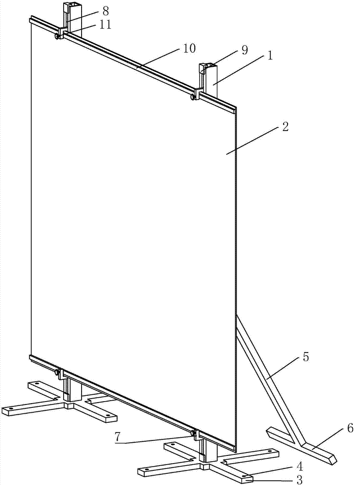
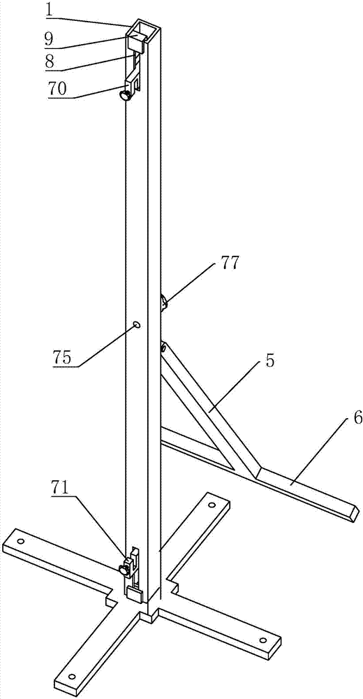
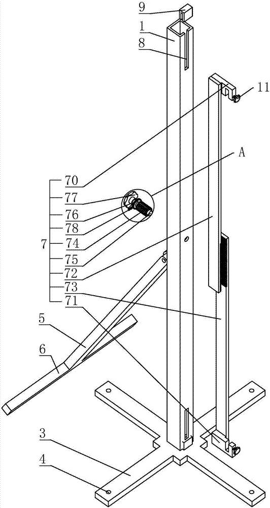
[0035] Embodiment 1: a kind of engineering fence, with reference to figure 1 , including hollow columns 1 arranged at intervals and a protective plate 2 arranged between the two columns 1 . Here, two columns 1 and a protective plate 2 are taken as examples. The column 1 is rectangular, and its lower end is connected with a base 3. The base 3 is in the shape of a "ten" and is welded by steel plates. On the four corners of the base 3, there are respectively a mounting hole 4 penetrating up and down. The mounting hole 4 is used for For cooperation with expansion bolts. The middle part of the column 1 is hinged with an auxiliary support rod 5 arranged obliquely, and the end of the auxiliary support rod 5 away from the hinge point is connected with a leg 6 arranged perpendicularly thereto. Auxiliary support bar 5 and support foot 6 are made of steel pipes, and both of them play the role of auxiliary support for the engineering fence, and are suitable for uneven or relatively soft...


PUM


Abstract

The invention discloses an engineering fence. The engineering fence is technologically characterized in that the engineering fence comprises hollow columns, a protection plate and clamping devices; sliding grooves are formed in the upper end and the lower end of each column; and each clamping device comprises an upper clamping slot which is connected with the sliding groove at the upper end of corresponding column in a sliding mode and is open downwards, an lower clamping slot which is connected with the sliding groove at the lower end of the corresponding column in a sliding mode and is open upwards, an upper rack vertically arranged at the upper end of the interior of the corresponding column, a lower rack vertically arranged at the lower end of the interior of the corresponding column, a transmission gear which can be engaged with the upper rack and the lower rack simultaneously, a rotary shaft with one end penetrating into the column which is connected to the transmission gear, a limiting gear arranged on the end, penetrating out of the column, of the rotary shaft, a driving piece used for driving the rotary shaft to rotate, and a limiting assembly used for limiting rotation of the limiting gear. The engineering fence solves the problem that an existing engineering fence is unsafe in use.

Description

technical field [0001] The invention relates to construction protection equipment, in particular to an engineering fence. Background technique [0002] When building a building, at first the house construction foundation pit will be excavated. After the house construction foundation pit is excavated, in order to prevent pedestrians and vehicles from falling into it, an engineering fence will be built around the house construction foundation pit. [0003] The existing engineering fence is mainly composed of columns and color steel plates. During installation, the columns are arranged at intervals around the foundation pit of the house, and then a color steel plate is set between every two columns. The lower ends of the columns are buried deep in the ground or It is connected to the ground through expansion bolts, and the two sides of the color steel plate are penetrated by steel wires and bound to the corresponding columns. Finally, all the color steel plates use the columns ...

Claims


Application Information

Patent Timeline
IPC IPC(8): E04H17/16
CPCE04H17/16
Inventor 吴广礼杨邵宾朱帝
Owner 北京四汇建筑工程有限责任公司
Why Eureka
Try Eureka