Particle injection system and annular particle accelerator

A particle accelerator and injection system technology, applied in accelerators, electrical components, etc., can solve problems such as increased storage beam disturbance, storage beam loss, storage beam instability, etc., to reduce the difficulty of overall design and manufacturing , The effect of reducing the required amount of magnetic field action

Active Publication Date: 2017-07-18
UNIV OF SCI & TECH OF CHINA
View PDF8 Cites 12 Cited by
  • Summary
  • Abstract
  • Description
  • Claims
  • Application Information

AI Technical Summary

Problems solved by technology

However, when multiple impact magnets are combined to operate, the pulse start time jitter and pulse amplitude jump from multiple impact magnets will disturb the stored beam current, and in severe cases, the stored beam current will be lost.
[0004] Therefore, in general, there are some problems in the protruding track injection process, for example: the process of moving the acceptance phase e

Method used


Image

  • Particle injection system and annular particle accelerator
  • Particle injection system and annular particle accelerator
  • Particle injection system and annular particle accelerator

Examples


Embodiment Construction

[0024] The following will clearly and completely describe the technical solutions in the embodiments of the present invention with reference to the accompanying drawings in the embodiments of the present invention. Obviously, the described embodiments are only some, not all, embodiments of the present invention. Based on the embodiments of the present invention, all other embodiments obtained by persons of ordinary skill in the art without making creative efforts belong to the protection scope of the present invention.

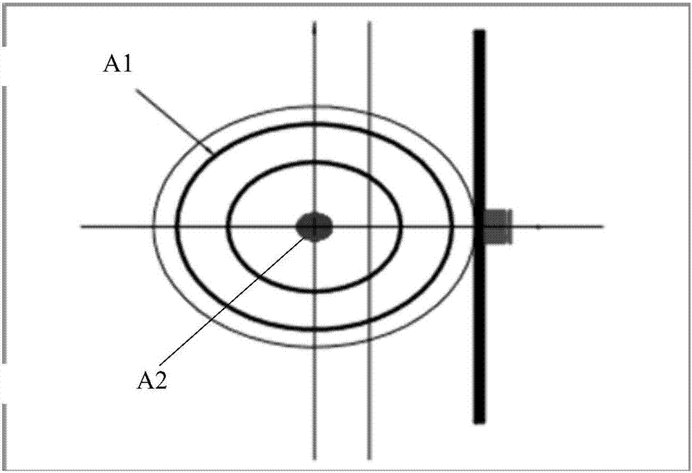
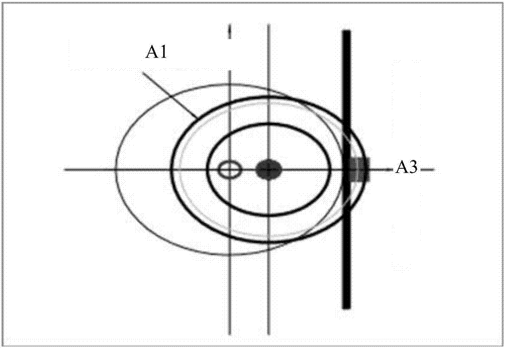
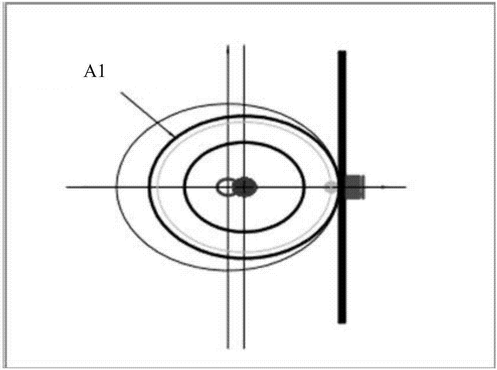
[0025] The embodiment of the present application provides a particle injection system, such as figure 2 As shown, applied to a circular particle accelerator, the particle injection system includes: a unidirectional magnet 10 and a jumping magnet 20; wherein,

[0026] The one-way magnet 10 is arranged on the side of the injection beam pipeline of the annular particle accelerator facing the closed track, and is used to provide a magnetic field to the side facin...


PUM


Abstract

The invention discloses a particle injection system and an annular particle accelerator. The particle injection system adopts jumping magnet to provide a pulse magnetic field having a preset cycle to an injection beam, and the jumping of the transmission speed and the transmission direction of the injection beam occur, when the injection beam passes through the incident gap of the jumping magnet, and the jumping of the emittance phase ellipse of the injection beam occurs, and therefore the emittance phase ellipse of the injection beam falls into the acceptability phase ellipse of the annular particle accelerator, and the injection process of the injection beam is completed. The ratio between pulse width of the pulse magnetic field provided by the jumping magnet and the circling cycle of the storage beam of the particle accelerator is smaller than a set value, and therefore the injection beam can be captured by the radio frequency acceleration electric field of the annular particle accelerator after entering the annular particle accelerator with help of a horizontal oscillation amplitude damping oscillation attenuation process. Because the pulse width of the pulse magnetic field is small, disturbances on the storage beam of the annular particle accelerator cannot be caused by the pulse magnetic field.

Description

technical field [0001] The present application relates to the technical field of accelerator physics, and more specifically, to a particle injection system and a circular particle accelerator. Background technique [0002] The circular particle accelerator is not only one of the important equipment for exploring particle physics, but also one of the important equipment for modern advanced light sources. The process of injecting particles into the circular particle accelerator is also an important stage of the circular particle accelerator. The process of injecting particles into the annular particle accelerator in the prior art is mostly the process of moving the acceptance phase ellipse of the annular particle accelerator by combining impact magnets or convex rail magnets, so that the acceptance phase ellipse covers the injection beam emission phase ellipse, Commonly known as convex rail injection process, the specific process refers to Figure 1(a), Figure 1(b), Figure 1(c)...

Claims


Application Information

Patent Timeline
IPC IPC(8): H05H7/00H05H7/04
CPCH05H7/001H05H7/04H05H2007/002H05H2007/048
Inventor 王相綦王琳刘刚文刘晓宇
Owner UNIV OF SCI & TECH OF CHINA
Why Eureka
Try Eureka