
Rotary integrated valve

An integrated valve and valve piece technology, applied in the field of reversing valves, can solve problems such as single angle of multi-channel valves, complex integrated valve structure, complex control system, etc., achieve corrosion-resistant service life, controllable and adjustable switching speed, avoid The effect of cross contamination

Active Publication Date: 2009-04-29
SHENZHEN MINDRAY BIO MEDICAL ELECTRONICS CO LTD +1
View PDF3 Cites 6 Cited by
  • Summary
  • Abstract
  • Description
  • Claims
  • Application Information

AI Technical Summary

Problems solved by technology

[0008] For the Chinese patent application whose publication number is CN1083570A, due to: 1) in order to ensure sealing, extra seals are used in many places, such as seals are provided between the valve plate and the outlet and inlet pipes, and between the valve body and the valve plate Sealing packing is filled between the shafts; 2) In order to ensure reliable reversing, high-hardness and high-strength alloy materials are embedded in the guide hole of the valve plate, the outlet and inlet pipe ends of the adjacent valve plate; so that the entire integrated valve complex structure
[0009] For the Chinese patent whose notification number is CN2291543Y, because: 1) a gear transmission system is used; 2) in order to prevent leakage, sealing rings are installed in the through holes of the upper and lower valve bodies, and a sealing protection ring is provided outside the rotating chip; 3) The control system is complex; 4) The angle is single, only a multiple of 30°; 5) It can only control the on-off of the liquid circuit, so the entire multi-channel valve has the disadvantages of single angle, single function, complex structure and complex control system

Method used


Image

  • Rotary integrated valve
  • Rotary integrated valve
  • Rotary integrated valve

Examples


Embodiment Construction

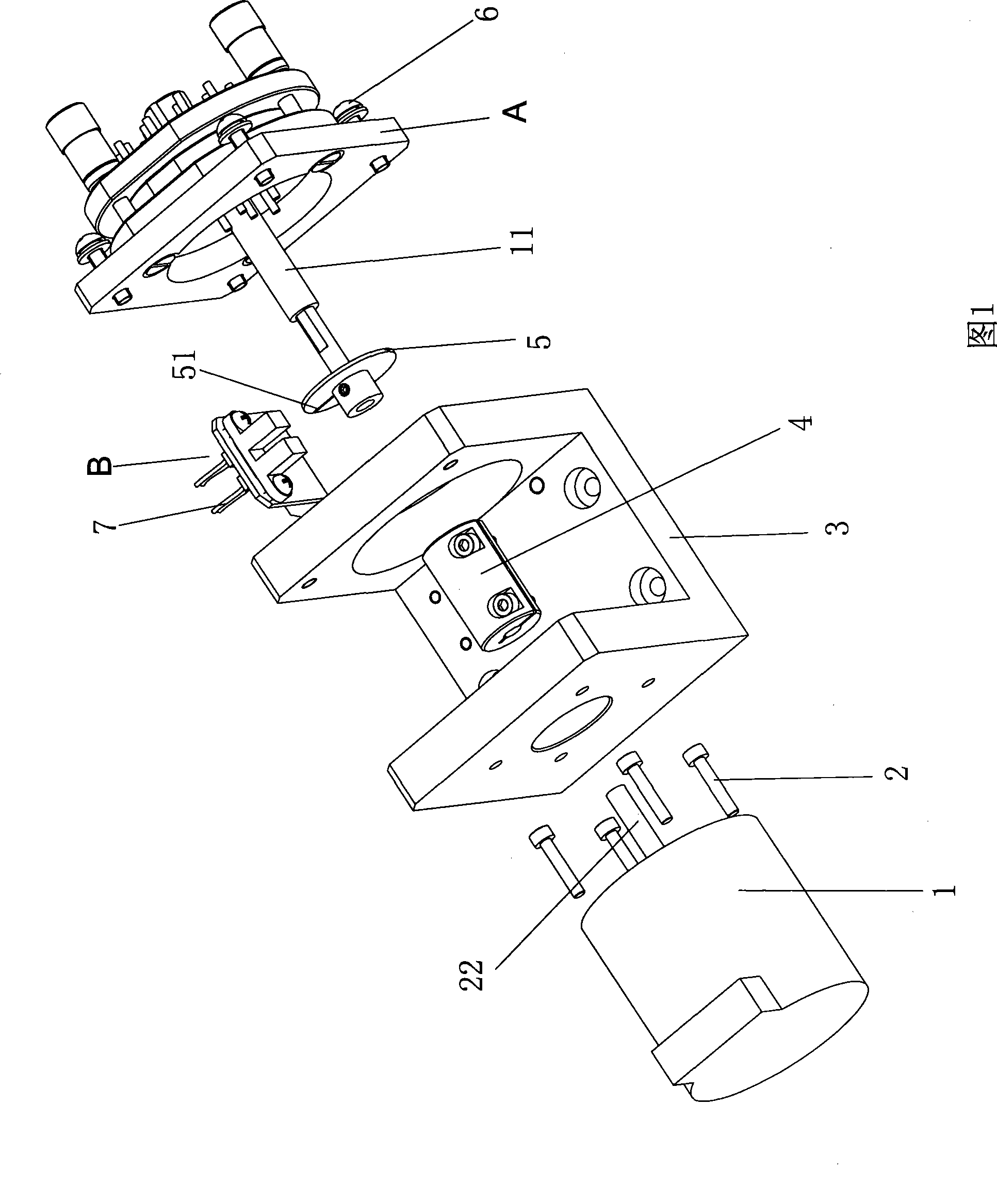
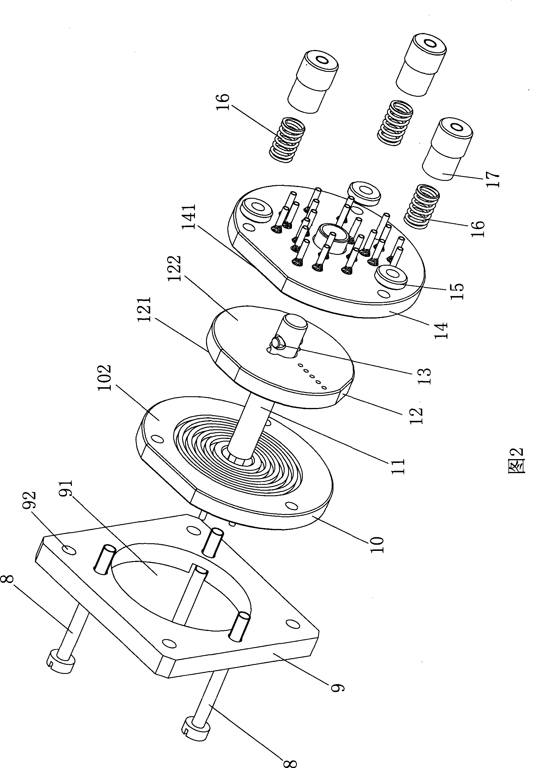
[0042] Figure 1 to Figure 9 As shown, the rotary integrated valve in this embodiment includes a driving mechanism 1 , a base 3 , a valve plate assembly A and a detection component B. The driving mechanism 1 is used to provide power, such as a stepping motor or a servo motor. The driving mechanism 1 is fixed on the base 3 through a fastener 2 , and the valve plate assembly A is fixed on the base 3 through a fastener 6 . The driving mechanism 1 has an output shaft (motor shaft of a stepping motor or a servo motor) 22, and the valve plate assembly A has a rotating shaft 11. The output shaft 22 and the rotating shaft 11 are coaxial and connected by a shaft coupling 4. The driving mechanism 1 drives the rotating shaft 11 to rotate. The detection part B includes a part 5 with a notch 51 and a photoelectric detection element 7 installed on the rotating shaft 11. The initial position of the rotating shaft 11 and the position during the rotation are detected and calibrated through t...


PUM


Abstract

The invention discloses a rotating integration valve, which comprises a driving mechanism having an output shaft and a valve plate assembly having a rotary shaft. The output shaft is in power connection with the rotary shaft, the valve plate assembly comprises a lower fixed valve plate, an upper fixed valve plate, and a moving valve plate arranged therebetween, the right end surface of the lower fixed valve plate is provided with m ring grooves having the same axis with the rotary shaft, each groove is provided with a joint hole penetrating to the left end surface of the fixed valve plate, the moving valve plate is provided with a plurality of penetrating switch holes communicating with the m grooves, the upper fixed valve plate is provided with n penetrating liquid discharging flow passages distributed on m circumferences having the same axis with the rotary shaft, wherein m and n are natural numbers not less than 2, and one circumference is provided with at least two liquid discharging flow passage and adjacent liquid discharging flow passages are partitioned by vacancies. The rotating integration valve can integrates a plurality of valves, and can realize the on-off and switch control for the fluid path.

Description

technical field [0001] The invention relates to the field of reversing valves, in particular to a reversing valve which uses the rotation of a movable valve plate relative to a fixed valve plate to realize switching of a liquid path. Background technique [0002] In the blood cell analyzer, due to the complexity of the liquid circuit system, multiple reversing valves are required to control the flow direction and on-off of the liquid. The most used are two-position two-way electromagnetic reversing valve and two-position three-way electromagnetic reversing valve. In addition, the various reagents used by blood cell analyzers to detect blood cells are corrosive to varying degrees. At present, it is difficult to find a type of electromagnetic reversing valve that can resist the long-term corrosion of different reagents. Such reversing valves lead to high cost and large volume of the whole instrument. In order to solve the above problems, an integrated valve is used in the pr...

Claims


Application Information

Patent Timeline
IPC IPC(8): F16K11/074
Inventor 颜彦廖常俊李乐昌
Owner SHENZHEN MINDRAY BIO MEDICAL ELECTRONICS CO LTD
Learn More