Draw bar box with charging device

A technology of charging device and trolley case, which is applied in the direction of measuring device, weighing indicating device, luggage case, etc., and can solve the problems of being placed in the case, inconvenience, waste of time, etc.

Inactive Publication Date: 2017-07-21
李志坚
View PDF10 Cites 3 Cited by
  • Summary
  • Abstract
  • Description
  • Claims
  • Application Information

AI Technical Summary

Problems solved by technology

[0002] Common trolley cases on the market usually only have a simple function of storing luggage. When people travel or go on a business trip with a trolley case, they put all their luggage in the case
With the more and more frequent use of electronic devices, the demand for power sources of electronic devices is increasing. If you go out for a long time, the mobile phone you carry with you must be charged from time to time. Now there are mobile power sources such as charging treasures to realize real-time charging. function, but when people go out, the power bank can only be placed in the box, so when charging is needed, the power bank must be taken out of the box to charge the mobile phone, which is a waste of time
Moreover, the power bank must be taken out of the suitcase when checked in, which is very inconvenient

Method used


Image

  • Draw bar box with charging device
  • Draw bar box with charging device
  • Draw bar box with charging device

Examples


Embodiment Construction

[0027] The content of the present invention will be described in detail below in conjunction with the accompanying drawings and specific embodiments of the description:

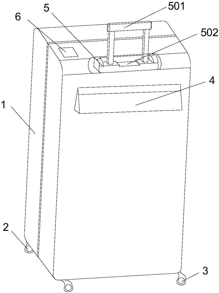
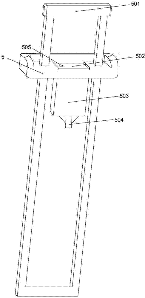
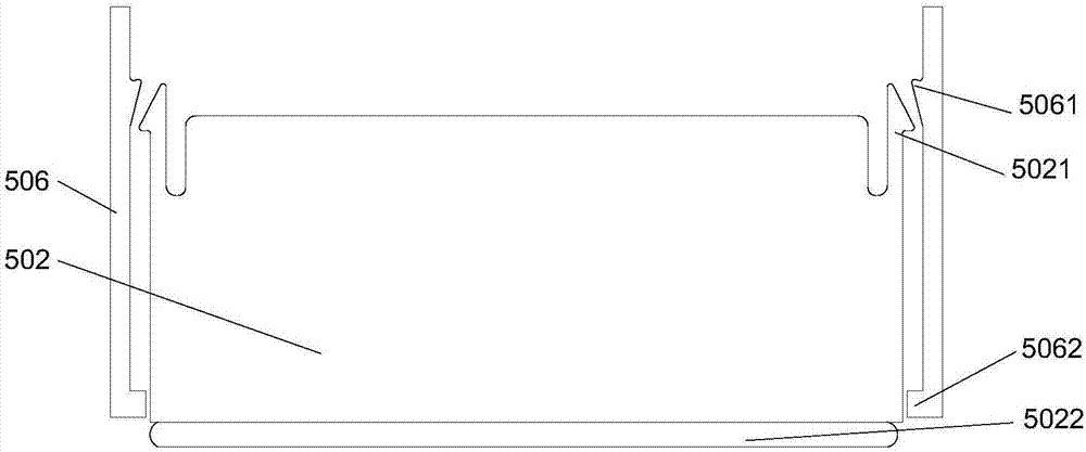
[0028] Such as Figure 1-5 , this embodiment provides a trolley case with a charging device, including a case 1, a trolley frame 5 mounted on the case 1, and a walking wheel mechanism mounted on the bottom of the case 1; the trolley frame 5 is provided with a Tow the retractable pull rod 501 of the box body 1, the pull rod frame 5 is provided with a charger accommodating cavity 503 for putting a charging device in the middle of the pull rod 501, and the upper part of the charger accommodating cavity 503 is set There is an opening, and sliding slots 506 are arranged on both sides of the opening, and a sliding cover 502 for covering or opening the opening is slidably installed in the sliding slots 506 .

[0029] In this embodiment, in order to fasten the sliding cover 502; the two sides of the sliding cover 50...


PUM


Abstract

The invention relates to a draw bar box with a charging device. The draw bar box comprises a box body, a draw bar frame mounted on the box body and a traveling wheel mechanism mounted at the bottom of the box body, wherein a telescopic draw bar for dragging the box body to move is arranged on the draw bar frame; a charger accommodating cavity which is located in the middle of the draw bar and is used for placing of the charging device is arranged on the draw bar frame; an opening is formed in the upper part of the charger accommodating cavity; sliding chutes are formed in two sides of the opening; and a sliding cover for covering the opening is mounted in the sliding chutes in a sliding manner. By external arrangement of an independent storage position of the charging device, the charging device can be conveniently taken at any time; furthermore, by the arrangement of the sliding cover, the charging device is difficult to fall off; by the arrangement of a spring, the charging device can pop out; besides, the charger accommodating cavity can be suitable for charging devices of various specifications; the specification of the charging device is in direct proportion to the compression deformation of the spring; when the charging device is larger in size, the spring is compressed to a larger extent; and when the charging device is smaller in size, the spring is compressed to a smaller extent.

Description

technical field [0001] The invention relates to the technical field of trolley cases, in particular to a trolley case with a charging device. Background technique [0002] Common trolley cases on the market usually only have a simple function of storing luggage, and people put their luggage into the suitcase when they travel or go on a business trip with them. With the more and more frequent use of electronic devices, the demand for power sources of electronic devices is increasing. If you go out for a long time, the mobile phone you carry with you must be charged from time to time. Now there are mobile power sources such as charging treasures to realize real-time charging. function, but the power bank can only be placed in the box when people go out, resulting in the need to take out the power bank from the box to charge the mobile phone when charging is needed, which is a waste of time. Moreover, the power bank must be taken out of the suitcase when checked in, which is v...

Claims


Application Information

Patent Timeline
Patent Type & Authority Applications(China)
IPC IPC(8): A45C5/04A45C5/14A45C13/00A45C13/26A45C13/38
CPCA45C5/045A45C5/14A45C13/001A45C13/262A45C13/385A45C13/28A45C15/00G01G19/58A45C5/04A45C2013/267G01G19/021G01G23/36
Inventor 李志坚
Owner 李志坚
Why Eureka
Try Eureka