Adsorption-type quick film sticking device

A film sticking device and adsorption device technology, which is applied in the direction of packaging material feeding device, packaging, transportation packaging, etc., can solve problems such as wrinkles, unstable film unfolding, and inability to achieve high-efficiency film sticking, so as to achieve accurate film sticking and stable film pulling process Effect

Inactive Publication Date: 2017-07-21
浙江班萘特复合材料股份有限公司
View PDF1 Cites 9 Cited by
  • Summary
  • Abstract
  • Description
  • Claims
  • Application Information

AI Technical Summary

Problems solved by technology

[0006] The purpose of the present invention is to address the deficiencies of the prior art, by setting the film traction part to absorb the traction film in a negative pressure mode and setting the feeding part above the film traction part to overco

Method used


Image

  • Adsorption-type quick film sticking device
  • Adsorption-type quick film sticking device
  • Adsorption-type quick film sticking device

Examples


Example Embodiment

[0047] Embodiment one

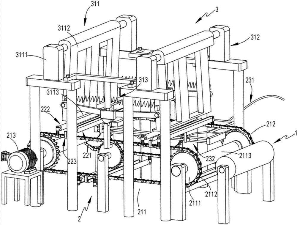
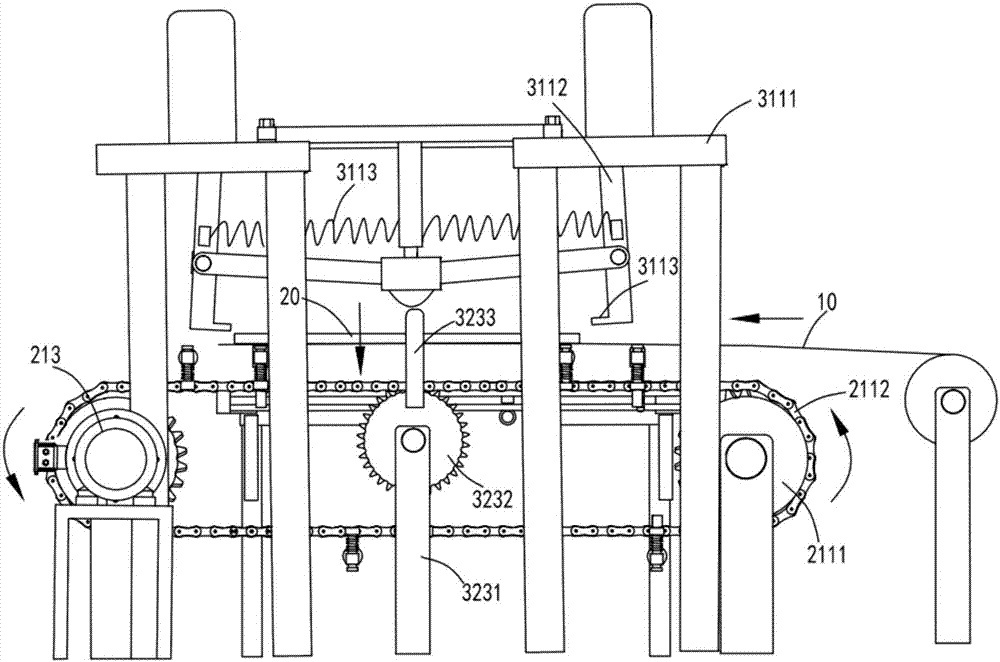
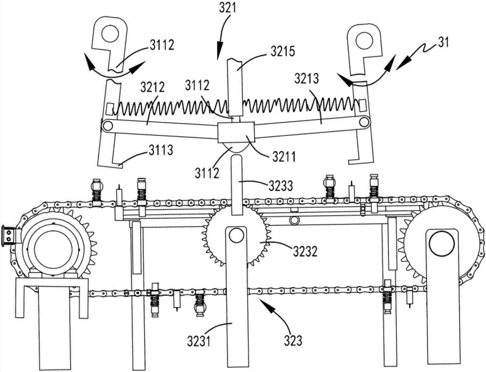
[0048] like figure 1 , figure 2 , image 3 , Figure 4 , Figure 5 , Image 6 and Figure 7 As shown, a kind of adsorption type fast film sticking device comprises film unwinding part 1, and described film unwinding part 1 is used for conveying film 10 backward; Film traction part 2, and described film traction part 2 is arranged on film unwinding part 1, the film traction part 2 is used to drive one end of the film 10 to move backward to make the film 10 spread out in the horizontal direction; the feeding part 3, the feeding part 3 is arranged on the upper end of the film traction part 2, The feeding part 3 is used to intermittently supply the sheet material 20 to the film pulling part 2 so that the sheet material 20 is bonded to the unfolded film 10; 21 driven by several groups of supporting cutting mechanism 22 and the negative pressure supply mechanism 23 arranged on one side of the rotary mechanism 21; the feeding part 3 includes a clamping...

Example Embodiment

[0058] Embodiment two

[0059] like figure 1 , figure 2 , image 3 , Figure 4 , Figure 5 , Image 6 and Figure 7 As shown, the components that are the same as or corresponding to those in the first embodiment are marked with the corresponding reference numerals in the first embodiment. For the sake of simplicity, only the differences from the first embodiment will be described below. The difference between the second embodiment and the first embodiment is that: the negative pressure generating device 231 includes a negative pressure tube 2311; The sliding support rod 2321 set in the transmission direction, the pressure supply terminal 2322 slidably arranged on the sliding support rod 2321, and the elastic member a2325 with one end fixed on the pressure supply terminal 2322 and the other end fixed on the fixed frame 2324, said A support piece 2323 is provided on the pressure supply end 2322, and a support block 2217 matched with the support piece 2323 is provided at ...


PUM


Abstract

The invention relates to an adsorption type fast film sticking device, which comprises a film unwinding part for conveying the film backward; a film pulling part for driving one end of the film to move backward to make the film unroll in a horizontal direction; a feeding part, the The feeding part is used to intermittently supply the sheet material to the film pulling part to make the sheet fit with the unfolded film; the film pulling part includes a rotating mechanism and several groups of supporting cutters which are arranged on the rotating mechanism and perform rotating motion under the driving of the rotating mechanism. A cutting mechanism and a negative pressure supply mechanism arranged on one side of the rotary mechanism; the feeding part includes a clamping mechanism for supporting the sheet material and a blanking material for controlling the sheet material in the clamping mechanism to fall intermittently with the rotation of the rotary mechanism Mechanism; the invention overcomes the problems of unstable film unfolding during the film sticking process, easy occurrence of wrinkles and inability to achieve continuous and efficient film sticking and complete film cutting while sticking the film.

Description

technical field [0001] The invention relates to the technical field of film sticking equipment, in particular to an adsorption type fast film sticking device. Background technique [0002] Some products on the market have a film attached to the surface. During the processing of this product, the film is usually attached to the product by hand. The accuracy of the film is low and the production efficiency is low. Therefore, there is an urgent need for a film laminating machine with high precision and high production efficiency. [0003] A Chinese invention patent with the application publication number CN105966962A discloses a film cutting machine, which effectively prevents the film from being deformed or broken due to excessive instantaneous tension by setting a buffer device between two guide rollers , but the device has the following issues: [0004] 1. The device has unstable traction during the film traction process and is prone to wrinkles during the film unfolding p...

Claims


Application Information

Patent Timeline
IPC IPC(8): B65B33/02B65B61/06B65B41/06
CPCB65B33/02B65B41/06B65B61/06
Inventor 金庭峰
Owner 浙江班萘特复合材料股份有限公司
Why Eureka
Try Eureka