
Automatic laminating device and method

A mobile device and sliding device technology, which is applied in the field of backlight, can solve the problems of low pass rate, low work efficiency, easy to be scratched, etc., and achieve the effect of improving precision and improving work efficiency

Pending Publication Date: 2018-12-18
惠州市福瑞尔光电有限公司
View PDF6 Cites 0 Cited by
  • Summary
  • Abstract
  • Description
  • Claims
  • Application Information

AI Technical Summary

Problems solved by technology

[0004] The purpose of the present invention is to solve the problems that the membrane in the artificial membrane method is easily polluted, easily scratched, poor installation accuracy, low work efficiency, and low pass rate

Method used


Image

  • Automatic laminating device and method
  • Automatic laminating device and method

Examples


Embodiment Construction

[0051] The following will clearly and completely describe the technical solutions in the embodiments of the present invention with reference to the drawings in the embodiments of the present invention. Apparently, the described embodiments are only some of the embodiments of the present invention, but not all of them. Based on the embodiments of the present invention, all other embodiments obtained by persons of ordinary skill in the art without creative efforts fall within the protection scope of the present invention.

[0052] In order to understand the content of the present invention more easily, the following definitions are made: taking the observer as a reference, the observer faces the drawing, the front in the content is the part near the observer in the figure, and the back in the content is the part far away from the observer in the figure The left part of the content is the left part of the observer in the figure, the right part of the content is the right part of ...


PUM


Abstract

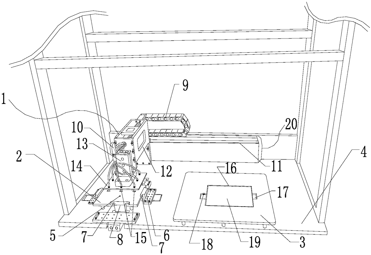
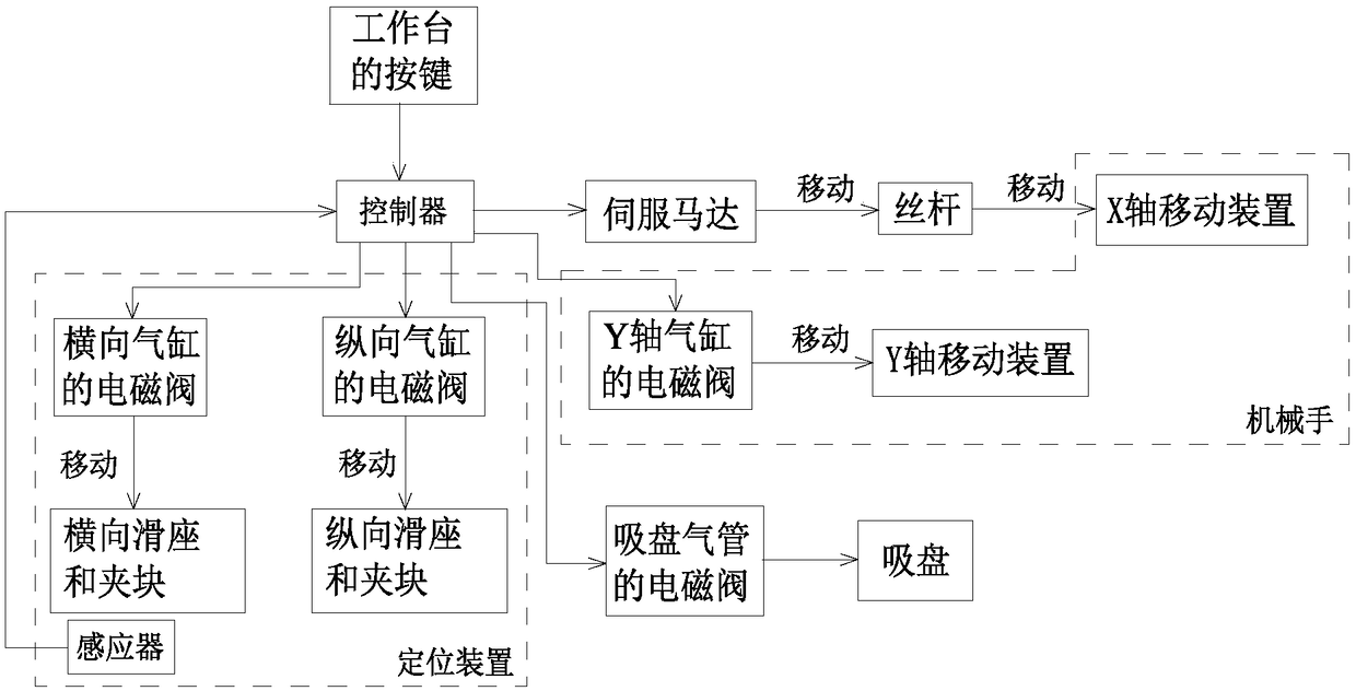
The invention provides an automatic laminating device. The automatic laminating device comprises a manipulator, a positioning table, a film attaching table, a workbench, a controller, a positioning device, an inductor and a sliding device. The positioning table is arranged at the center of the positioning device. The positioning device is located on the left portion of the workbench. The film attaching table is located on the right portion of the workbench. The inductor is arranged in the middle of the positioning table. The sliding device is horizontally arranged on the rear edge of the workbench, and the two ends of the sliding device separately stretch across the positioning table and the film attaching table. The positioning device comprises two opposite horizontal sliding bases, two opposite horizontal clamping blocks, two opposite longitudinal sliding bases and two opposite longitudinal clamping blocks. The sliding device comprises a tank chain, a servo motor, a sliding rail anda lead screw. The manipulator comprises an X-axis moving device, a Y-axis moving device, a grabbing plate, a suction cup and a Y-axis cylinder. By adoption of the automatic laminating device, the problems that during manual film attaching, films are likely to be polluted and scratched, the installation precision is poor, the working efficiency is low, and the qualification rate is low are solved.

Description

technical field [0001] The invention relates to the field of backlight sources, in particular to an automatic film coating device and method. Background technique [0002] During the assembly process of the backlight source, multiple light-enhancing films, diffusion films or protective films must be put into the backlight shell one by one according to the order specified in the design requirements, so as to achieve the uniformity and uniformity of the LED backlight. transparency. At present, the general manufacturers are assembled by manual film installation. Although this method is simple and feasible, there are many defects: the diaphragm is easily polluted, easily scratched, poor installation accuracy, low work efficiency, and low pass rate. [0003] In order to overcome the above-mentioned problems, we have invented a device and method for automatic film covering. Contents of the invention [0004] The purpose of the present invention is to solve the problems of eas...

Claims


Application Information

Patent Timeline
Patent Type & Authority Applications(China)
IPC IPC(8): B65B33/02
CPCB65B33/02
Inventor 徐缘钦谢海滨虢智荣陈智文
Owner 惠州市福瑞尔光电有限公司
Learn More