Motor-controlled automatic walking and unreeling and tipping prevention wire roller for electricity

A motor control and self-propelled technology, applied in the field of online rollers, can solve the problems of increasing pay-off time, reducing work efficiency, and simple structure

Pending Publication Date: 2017-07-21
国网湖北省电力有限公司荆门供电公司 +1
View PDF0 Cites 2 Cited by
  • Summary
  • Abstract
  • Description
  • Claims
  • Application Information

AI Technical Summary

Problems solved by technology

[0002] At present, the existing wire rollers have a simple structure, and most of them require people to drive and control the wire rollers to pay off the wires. At the same time, when it is difficult to walk between two poles, the existing wire rollers still need people to control them. And unwinding, so that people not only need to walk on difficult roads, but also need continuous unwinding, which will undoubtedly increase the time for unwinding and reduce work efficiency, so it is necessary to design a motor control self-propelled unwinding for electric power. Wire rollers for wire anti-tipping

Method used


Image

  • Motor-controlled automatic walking and unreeling and tipping prevention wire roller for electricity
  • Motor-controlled automatic walking and unreeling and tipping prevention wire roller for electricity
  • Motor-controlled automatic walking and unreeling and tipping prevention wire roller for electricity

Examples


Embodiment Construction

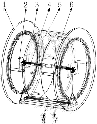
[0035] please see Figure 1 to Figure 16 . Such as figure 1 , 2 As shown, it includes an adjustment mechanism 4, a traveling mechanism 43, a trigger mechanism 8, such as figure 1 , 2 As shown, wherein the regulating mechanism 4 and the triggering mechanism 8 are all installed on the traveling mechanism 43 .

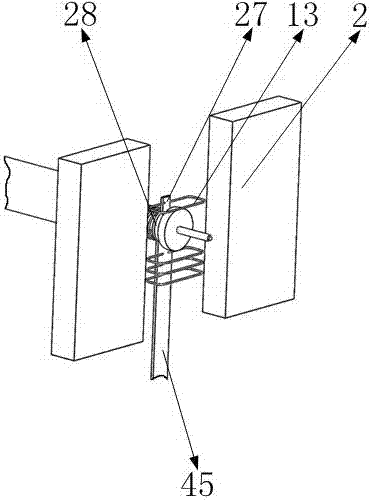
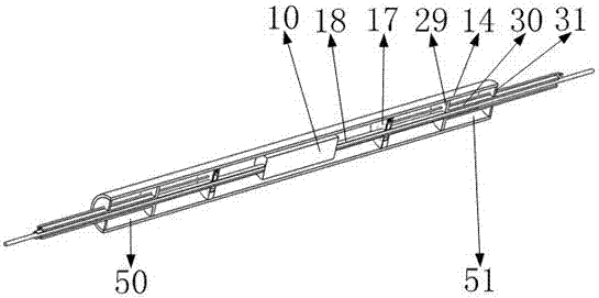
[0036] Such as figure 1 , 2 As shown, the above-mentioned traveling mechanism 43 includes a wire wheel 1, a generator magnet 2, a scroll spring 46, a telescopic rod 3, a support column 6, a T-ring 9, a motor 10, a T-ring 9 slots, a hollow sleeve 18, a battery 7, Drive ladder shaft 23, battery 7 fixed plates, magnet ring 24, fixed bar 25, coil 13, coil 13 fixed plates, fixed circular plate 28, as figure 1 , 2 Shown, wherein the two ends of motor 10 all have motor 10 axles; As figure 1 , 2 As shown, the two hollow sleeves 18 are all nested on the outer surface of the motor 10 shaft and the two hollow sleeves 18 are symmetrically installed on the two ends of the mo...


PUM


Abstract

The invention belongs to the technical field of wire rollers, and particularly relates to a motor-controlled automatic walking and unreeling and tipping prevention wire roller for electricity. The wire roller comprises an adjusting mechanism, a walking mechanism and a trigger mechanism, wherein the adjusting mechanism and the trigger mechanism are mounted on the walking mechanism. The wire roller has the functions of automatically walking and unreeling wires, automatically adapting to and adjusting driving torque, and preventing tipping due to nonuniform roller stress, and protecting the environment; the adjusting mechanism has the function of automatically adjusting driving force of a motor according to the ground condition; and the walking mechanism has the function of driving the wire roller to move to automatically unreel the wires.

Description

technical field [0001] The invention belongs to the technical field of wire rollers, and in particular relates to a wire roller used for electric motor control self-propelled pay-off and anti-dumping. Background technique [0002] At present, the existing wire rollers have a simple structure, and most of them require people to drive and control the wire rollers to pay off the wires. At the same time, when it is difficult to walk between two poles, the existing wire rollers still need people to control them. And unwinding, so that people not only need to walk on difficult roads, but also need continuous unwinding, which will undoubtedly increase the time for unwinding and reduce work efficiency, so it is necessary to design a motor control self-propelled unwinding for electric power. Wire rollers for wire anti-tipping. [0003] The present invention designs a motor-controlled self-propelled pay-off anti-dumping wire roller used for electric power to solve the above problems....

Claims


Application Information

Patent Timeline
IPC IPC(8): B65H49/34
CPCB65H49/34B65H2701/30B65H2403/92
Inventor 汪燚春陈且青王昆杨帆胡若琳
Owner 国网湖北省电力有限公司荆门供电公司
Why Eureka
Try Eureka