Eureka AIR delivers breakthrough ideas for toughest innovation challenges, trusted by R&D personnel around the world.

Full-automatic liquid loading crane pipe and application thereof

A fully automatic technology for loading cranes, applied in the directions of liquid distribution, conveying or transfer devices, packaging, distribution devices, etc. good question

Active Publication Date: 2017-07-21
BEIJING MOUNTAIN IND
View PDF9 Cites 7 Cited by
  • Summary
  • Abstract
  • Description
  • Claims
  • Application Information

AI Technical Summary

Problems solved by technology

At present, the liquid sulfur loading crane tubes on the market contain various forms of heat tracing structures, but the overall heat tracing effect is not good or there is local heat tracing, which also causes the liquid sulfur to drop in temperature when passing through the loading crane tubes, so that Viscosity increases or becomes solid to block the pipeline. In severe cases, the movable rotating parts of the crane tube body solidify and stagnate and cannot work, which will eventually affect the loading of liquid sulfur

Method used


Image

  • Full-automatic liquid loading crane pipe and application thereof
  • Full-automatic liquid loading crane pipe and application thereof
  • Full-automatic liquid loading crane pipe and application thereof

Examples


Embodiment Construction

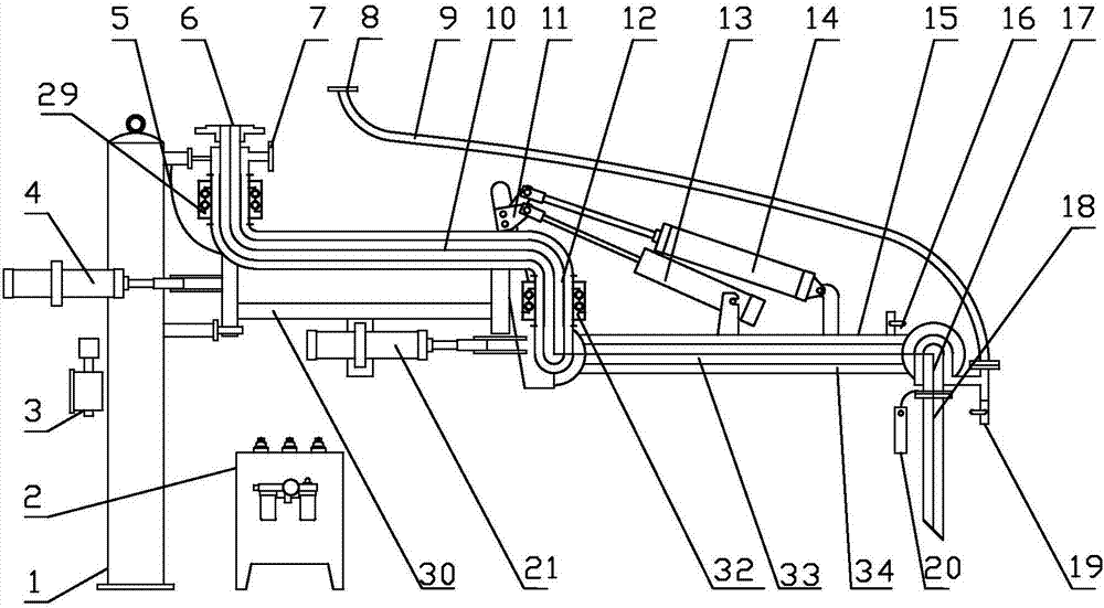
[0022] Such as figure 1 As shown, the automatic fluid loading crane of the present invention includes a conveying crane 33 and a heat tracing sleeve 34 sleeved on the conveying crane 33. The heat tracing sleeve 34 is connected with a steam hose 9, and the conveying crane 33 is connected to the crane tube column 1, the crane tube column 1 supports the delivery crane tube 33, the heat tracing sleeve 34 is set on the delivery crane tube 33, and the space between the heat tracing sleeve 34 and the delivery crane tube 33 transports steam, The steam provides heat for the transporting crane pipe 33 , so that the fluid in the transporting crane pipe 33 can be transported stably, and the steam hose 9 transports heat transfer steam for the heating sleeve 34 .

[0023] The conveying crane pipe 33 includes an inner arm 10, an outer arm 15 and a drop arm 18 connected in sequence, an elbow assembly 12 is connected between the outer arm 15 and the inner arm 10, and a drop arm assembly is con...


PUM


Abstract

The invention provides a full-automatic liquid loading crane pipe and application thereof, and belongs to the field of liquid conveying equipment. The full-automatic liquid loading crane pipe is uniform in heat tracing, automatic to control, accurate to adjust, safe, reliable, simple and convenient to operate. The full-automatic liquid loading crane pipe comprises a conveying crane pipe, and a heat tracing sleeve which sleeves the conveying crane pipe, wherein a steam hose communicates with the heat tracing sleeve; the conveying crane pipe comprises an inner arm, an outer arm and a vertical arm which are sequentially connected; an elbow assembly is connected between the outer arm and the inner arm; a first driving part and a first transmission rack are connected to the inner arm; the first driving part is connected with the first transmission rack, and the first transmission rack is connected with a second driving part; an angle adjusting rack which is connected to the elbow assembly is connected with the second driving part; a balancing driving part and an adjusting driving part which are connected to the outer arm are connected to the angle adjusting rack; sleeve type rotating joints are connected to the inner arm and the elbow assembly.

Description

technical field [0001] The invention relates to the field of fluid conveying equipment, in particular to a fully automatic fluid loading crane and its application. Background technique [0002] The crane tube is a special equipment in the process of fluid loading and unloading in the petrochemical industry, also known as the fluid loading and unloading arm. Crane pipes are connected by rotary joints with rigid pipes and elbows to realize movable equipment for transporting liquid media between trains, car tankers and trestle storage and transportation pipelines, replacing the old-fashioned hose connections, with high safety. Features such as flexibility and long life. The crane tube is mainly composed of fixing, rotating, operating, balancing and other mechanisms and oil pipes. [0003] At normal temperature, sulfur is solid, but above 119°C it is liquid. Liquid sulfur has the lowest viscosity at 135-145°C and is most suitable for transportation. In the temperature range a...

Claims


Application Information

Patent Timeline
Patent Type & Authority Applications(China)
IPC IPC(8): B67D7/42B67D7/82
CPCB67D7/42B67D7/82
Inventor 李小明狄延龙王海文谢登胜陈力峰王积新洪胜松
Owner BEIJING MOUNTAIN IND
Why Eureka
Eureka Blog
Learn More