

Non-foundation post pressing pile implementation method
A realization method and basic technology, applied in the field of special civil engineering construction, can solve problems such as pressing into the soil, connecting existing foundations, restricting the application of reconstruction and expansion of existing buildings, etc.
- Summary
- Abstract
- Description
- Claims
- Application Information
AI Technical Summary
Problems solved by technology
Method used
Image

Examples
Embodiment 1
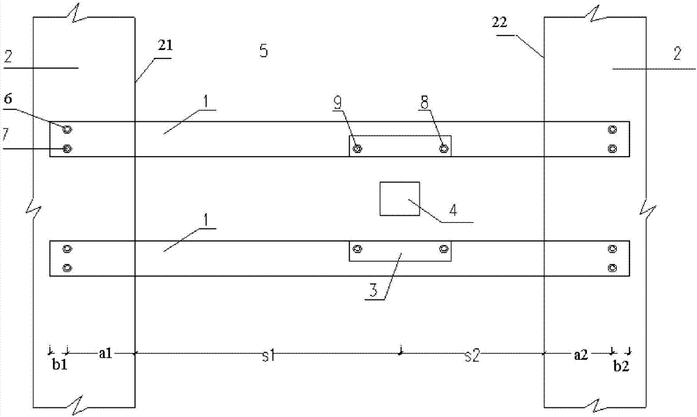
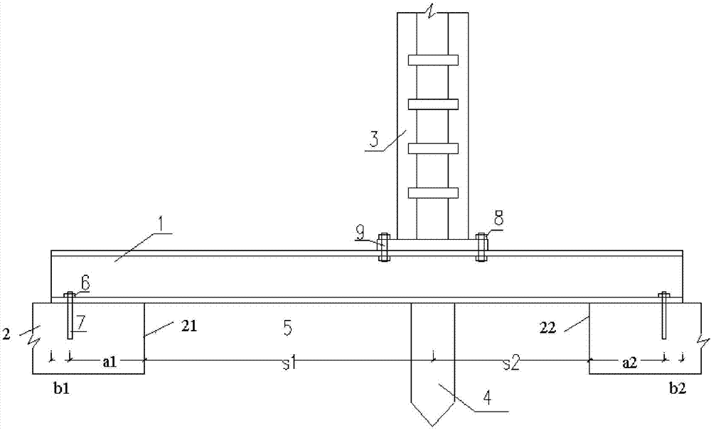
[0034] Embodiment 1, a method for realizing post-pile without foundation, that is, the method of post-pile on foundation soil without foundation; between two existing foundations 2 is foundation soil 5 at no foundation;
[0035] Set two parallel reaction beams 1 between two existing foundations 2; set bolts 7 on each existing foundation 2, and set nuts 6 matching the bolts 7 at both ends of the reaction beam 1 , so as to realize the fixed connection between the reaction beam 1 and the existing foundation 2; a pile frame 3 is set on each of the two reaction beams 1, and the two pile frames 3 correspond to each other; The pressure pile 4; the reaction beam 1 is made of section steel.
[0036] Include the following steps:
[0037] 1), first, according to the actual needs of the construction, set the position of the pressure pile 4 on the foundation soil 5 at the place without foundation;
[0038] Determine the distance between the center of the pressure pile 4 and the edge I21 ...
PUM
 Abstract
Description
Claims
Application Information