a detachment mechanism

A technology of anti-separation part and lifting lug, applied in drill pipe, casing, drill pipe, etc., can solve the problems of abnormal opening of stopper, poor working stability, easy slippage of stopper pin, etc., so as to improve safety, reliability, reduce Small chance of accidental touch and the effect of ensuring the stability of anti-dropping

Active Publication Date: 2019-09-10
CHENGDU ZHUOXIN IND
View PDF6 Cites 0 Cited by
  • Summary
  • Abstract
  • Description
  • Claims
  • Application Information

AI Technical Summary

Problems solved by technology

[0007] The elevator anti-off device disclosed in this patent document is relatively convenient for loading and unloading of the lifting ring, but since the cushion block is fixed on the boom of the elevator through the stop pin, the stop block of the lifting ring is connected with the block through the fixing pin, and the anti-off The device works frequently, and the stop pin also has wear problems after long-term use. The stop pin is easy to slip off, resulting in the failure of the anti-off device and poor working stability; moreover, the entire anti-off device is located outside the ear hole of the lifting lug. At this time, due to the surrounding environmental factors, the stopper is prone to false triggering, the stopper is opened abnormally, and the lifting ring slips off, causing a safety accident.

Method used


Image

  • a detachment mechanism
  • a detachment mechanism
  • a detachment mechanism

Examples


Embodiment 1

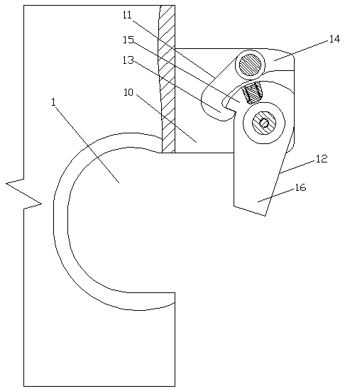
[0036] An anti-dropping mechanism includes a stopper 12 rotatably connected to the upper notch 10 of the lifting lug, and also includes a locking block 11 rotatably connected to the upper lug notch 10, the locking block 11 and the stop 12 For locking connection, the locking block 11 includes a locking hook portion 13 and a force receiving portion 14, the stop block 12 includes a locking portion 15 and an anti-falling portion 16, and the locking portion 15 is located in the upper notch 10 of the lifting lug Inside, the anti-dropping portion 16 is located in the ear hole 1 of the ear; the stopper 12 makes a pendulum movement, the stopper 12 swings clockwise to lock with the lock hook portion 13 of the lock block 11, and the lock hook portion 13 is in the lower In the pressed state, the stop block 12 swings counterclockwise to unlock the lock block 11, and the lock hook portion 13 is in a raised state.

[0037] This embodiment is the most basic implementation, and it also includes a...

Embodiment 2

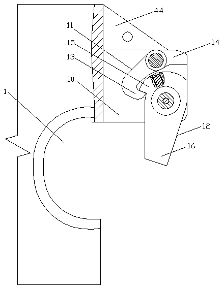
[0039] An anti-dropping mechanism includes a stopper 12 rotatably connected to the upper notch 10 of the lifting lug, and also includes a locking block 11 rotatably connected to the upper lug notch 10, the locking block 11 and the stop 12 For locking connection, the locking block 11 includes a locking hook portion 13 and a force receiving portion 14, the stop block 12 includes a locking portion 15 and an anti-falling portion 16, and the locking portion 15 is located in the upper notch 10 of the lifting lug Inside, the anti-dropping portion 16 is located in the ear hole 1 of the ear; the stopper 12 makes a pendulum movement, the stopper 12 swings clockwise to lock with the lock hook portion 13 of the lock block 11, and the lock hook portion 13 is in the lower In the pressed state, the stop block 12 swings counterclockwise to unlock the lock block 11, and the lock hook portion 13 is in a raised state.

[0040] The lock block 11 and the stop block 12 are in a one-way lock connection...

Embodiment 3

[0045] An anti-dropping mechanism includes a stopper 12 rotatably connected to the upper notch 10 of the lifting lug, and also includes a locking block 11 rotatably connected to the upper lug notch 10, the locking block 11 and the stop 12 For locking connection, the locking block 11 includes a locking hook portion 13 and a force receiving portion 14, the stop block 12 includes a locking portion 15 and an anti-falling portion 16, and the locking portion 15 is located in the upper notch 10 of the lifting lug Inside, the anti-dropping portion 16 is located in the ear hole 1 of the ear; the stopper 12 makes a pendulum movement, the stopper 12 swings clockwise to lock with the lock hook portion 13 of the lock block 11, and the lock hook portion 13 is in the lower In the pressed state, the stop block 12 swings counterclockwise to unlock the lock block 11, and the lock hook portion 13 is in a raised state.

[0046] The lock block 11 and the stop block 12 are in a one-way lock connection...


PUM


Abstract

The invention discloses an anti-drop mechanism and belongs to the technical field of petroleum drilling equipment. The anti-drop mechanism comprises a check block and further comprises a lock-up block. The lock-up block is connected with the check block in a lock-up mode. The lock-up block comprises a lock hook part and a force bearing part. The check block comprises a lock-up part and an anti-drop part. The lock-up part is located in a lifting lug upper notch. The anti-drop part is located in a lifting lug hole. The check block makes pendulum-type movement and swings clockwise to be locked with the lock hook part of the lock-up block, and accordingly the lock hook part is in a pressed state; and the check block swings anticlockwise to be unlocked with the lock-up block, and accordingly the lock hook part is in an uplift state. The check block is connected with the lock-up block in a lock-up mode, so that locking is reliable, and the stability of the check block is greatly guaranteed. Due to the fact that the lock-up block is located in the lifting lug upper notch, the lock-up block is not exposed on the outer side of an elevator, so that wrong touching of the lock-up block can be effectively avoided, safe reliability in the operation process is greatly improved, and the safety accident is avoided.

Description

Technical field [0001] The invention relates to the technical field of oil drilling equipment, in particular to an anti-drop mechanism. Background technique [0002] In drilling engineering, elevators are tools used to lift pipes such as drill pipes, tubing and casing. It is hung in the hoisting rings on both sides of the hoisting system hook, so that the drilling tool, tubing and casing can be lifted out or run into the wellbore. [0003] In the actual use process, due to the influence of various factors such as the environment, the lifting ring is easy to slip out of the ear hole of the elevator, causing a major safety accident. In order to prevent the lifting ring from falling out of the ear hole of the elevator, the elevator is usually provided with an anti-drop device. The anti-drop device in the prior art mostly adopts a pin structure, and a longitudinal pin hole is provided at the ear of the elevator, and the plug is inserted into the pin hole The inside can prevent the li...

Claims


Application Information

Patent Timeline
Patent Type & Authority Patents(China)
IPC IPC(8): E21B19/06
Inventor 陈伦俊邹益文卢伟池振华
Owner CHENGDU ZHUOXIN IND
Why Eureka
Try Eureka