Method for operating a pneumatically driven device for handling workpieces and device for handling workpieces

A pneumatic drive and equipment technology, applied in the direction of mechanical equipment, electrical components, manufacturing tools, etc., can solve problems such as assembly costs that are prone to failure, complex communication devices, etc.

Active Publication Date: 2021-07-02
J SCHMALZ GMBH
View PDF7 Cites 0 Cited by
  • Summary
  • Abstract
  • Description
  • Claims
  • Application Information

AI Technical Summary

Problems solved by technology

The communication devices used are relatively complex, which leads to failure-prone and additional assembly effort

Method used


Image

  • Method for operating a pneumatically driven device for handling workpieces and device for handling workpieces
  • Method for operating a pneumatically driven device for handling workpieces and device for handling workpieces
  • Method for operating a pneumatically driven device for handling workpieces and device for handling workpieces

Examples


Embodiment Construction

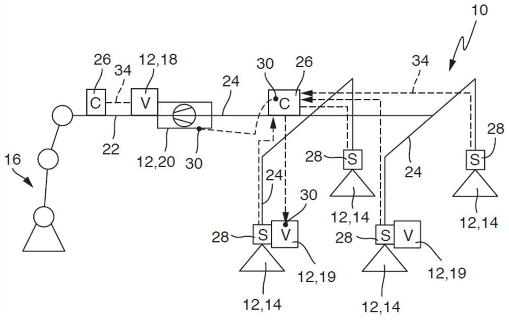
[0030] The method according to the invention and the device according to the invention are exemplarily referred to figure 1 A device 10 for manipulating workpieces is illustrated schematically in FIG. The device 10 is designed as a pneumatic device and includes a set of pneumatic units 12 .

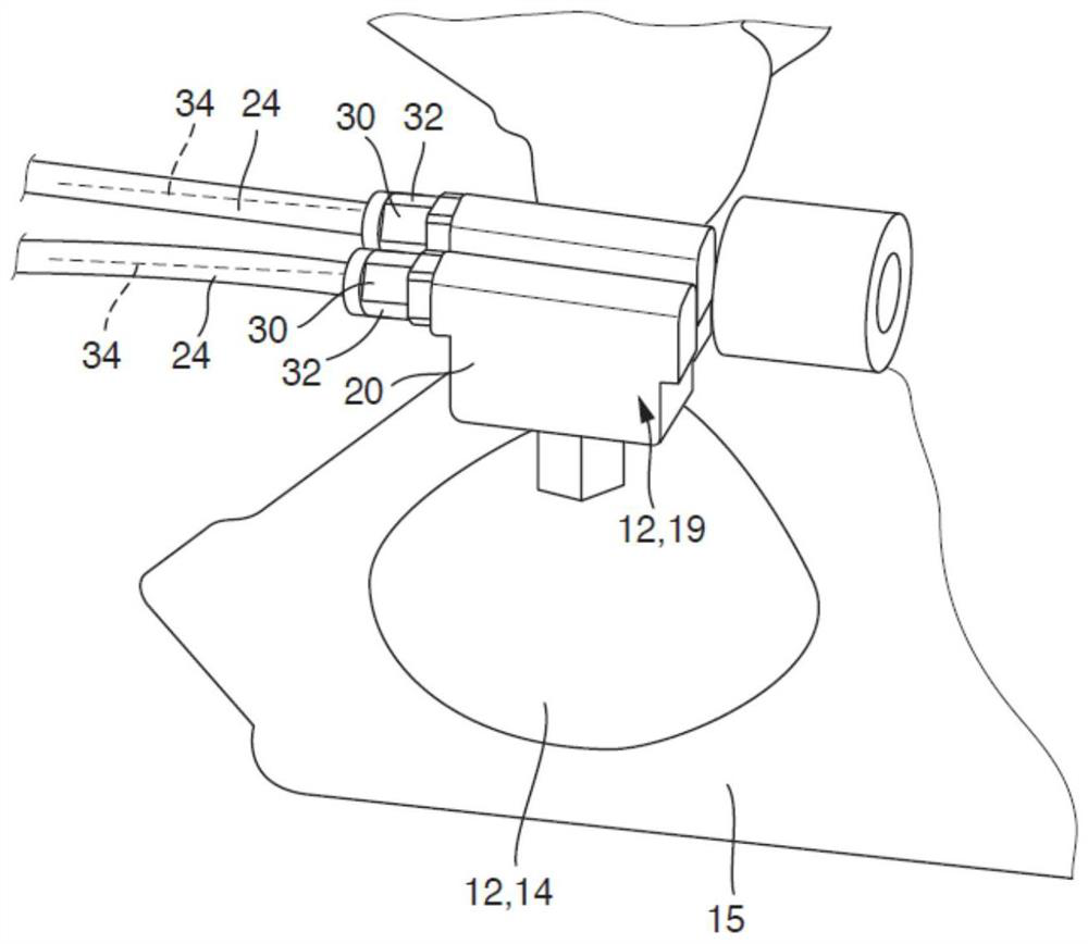
[0031] In the example shown, the pneumatic unit 12 comprises a plurality of suction grab devices 14 constituting the operating actuators 14 of the device 10 . The suction grab device 14 can be arranged on a suitable base frame (not shown in detail). Workpieces that extend spatially can also be secured with this overall arrangement. In order to move the actuator 14 spatially, an actuator 16 can be provided, for example in the form of a robot arm (in figure 1 shown only schematically).

[0032] Furthermore, the device 10 includes further pneumatic units, such as a valve device 18 and a control valve 19 for actuating the actuator 14 . In order to supply the suction grab device 14 with t...


PUM


Abstract

The invention relates to a method for operating a pneumatically driven device for handling workpieces, said device having a plurality of pneumatically operable or pneumatically controlled pneumatic units (12) Tubes (22, 24) are connected and / or fluidly connected to each other by means of pressure hoses (22, 24) and have at least one control unit (26) for controlling the air pressure in the pneumatic unit (12) by means of electrical signals Electrical signals of at least one pneumatic unit and / or for receiving and evaluating at least one of the pneumatic units (12). In this case, the electrical signals are transmitted between the control unit (26) and at least one pneumatic unit (12) via the pressure hoses (22, 24), wherein at least two different pressure hoses (22 , 24), the at least two pressure hoses connect the control unit (26) with the corresponding pneumatic unit (12). The invention also relates to a device operated according to the method.

Description

technical field [0001] The invention relates to a method for operating a pneumatically driven device for handling workpieces according to the preamble of claim 1 and a device for handling workpieces according to the preamble of claim 4 . Background technique [0002] Such methods and devices are used, for example, in production or processing lines. In particular, it concerns pneumatically operated systems with at least one vacuum generator driven by compressed air (e.g. an injector), which is fluidly connected to an operating device (such as a vacuum grab or actuator) connected to supply the necessary negative pressure to operate the device. In general, the device comprises a plurality of pneumatic functional units, which are connected with pressure hoses. [0003] In order to control the pneumatic functional unit as required, the device usually also includes a corresponding control unit. The required communication between the control unit and the pneumatic functional un...

Claims


Application Information

Patent Timeline
Patent Type & Authority Patents(China)
IPC IPC(8): G05B19/042H01R11/01
CPCG05B19/0423H01R11/01G05B2219/25257B25J15/0625F04F5/52B25J15/0052B65G47/917F16L11/127G05D16/2006G05D16/2066
Inventor 沃尔特·邓克曼托马斯·霍莱切克
Owner J SCHMALZ GMBH
Why Eureka
Try Eureka