Packaging structure of multi-channel parallel optical components and multi-channel parallel optical components

A technology of packaging structure and optical components, which is applied in the field of optical communication, can solve the problems of inability to meet the needs of product miniaturization, the inability to realize the effective transmission of optical signals, and the expansion of the size of the tailpipe, etc., to achieve high airtightness, small package size, high reliability effect

Active Publication Date: 2019-08-16
HISENSE & JONHON OPTICAL ELECTRICAL TECH CO LTD
View PDF5 Cites 0 Cited by
  • Summary
  • Abstract
  • Description
  • Claims
  • Application Information

AI Technical Summary

Problems solved by technology

[0004] At present, the two methods are more suitable for the coaxial packaging scheme of a single optical fiber. For multi-channel transmission optical modules (that is, multi-channel parallel optical modules), the housing with glass optical windows is limited by the inner and outer optical paths of the housing. It is difficult to realize the effective transmission of optical signals, and welding and assembling sealing rings on multi-channel parallel optical fiber ribbons requires greatly expanding the size of the tail pipe, which cannot meet the miniaturization requirements of the product.

Method used


Image

  • Packaging structure of multi-channel parallel optical components and multi-channel parallel optical components
  • Packaging structure of multi-channel parallel optical components and multi-channel parallel optical components
  • Packaging structure of multi-channel parallel optical components and multi-channel parallel optical components

Examples


Embodiment Construction

[0028] In order to make the purpose, technical solutions and advantages of the embodiments of the present invention clearer, the technical solutions in the embodiments of the present invention will be described clearly and completely below with reference to the accompanying drawings in the embodiments of the present invention.

[0029] In the description of the present invention, it should be understood that the terms "first", "second", "third" and "fourth" are only used for descriptive purposes and should not be construed as indicating or implying relative importance. , the orientation or positional relationship indicated by the terms "top", "bottom", etc. is based on the orientation or positional relationship shown in the accompanying drawings, and is only for the convenience of describing the present invention and simplifying the description, rather than indicating or implying the indicated device or element. It must have a specific orientation, be constructed and operate in...


PUM


Abstract

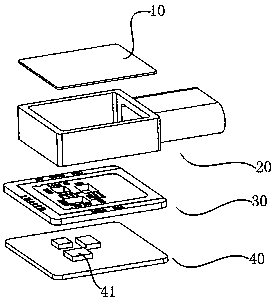
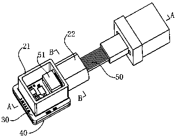
The present invention discloses a multi-path parallel optical assembly packaging structure and a multi-path parallel optical assembly having the packaging structure. The packaging structure comprisesa top plate, an intermediate shell and a bottom plate, the intermediate shell comprises an annular frame and a tail tube, the annular frame is used to form an airtight cavity with the top plate and the bottom plate, and the tail tube and the annular frame are molded integrally and are communicated with the airtight cavity. The bottom plate comprises a substrate and a metal plate, the substrate isequipped with an internal wiring terminal located inside the airtight cavity, a chip loading hole and an external wiring terminal located outside the airtight cavity, and the metal plate is soldered on the bottom surface of the substrate and seals the chip loading hole, wherein after an optical joint at one end of a multi-path parallel optical fiber ribbon penetrates the tail tube and enters the annular frame, the tail tube and the multi-path parallel optical fiber ribbon are sealed via the solders. According to the present invention, via the airtight cavity, the key components are sealed effectively, by a mode that the tail tube is sealed by the solders, the large scale of a product is avoided while the optical signals are transmitted reliably, and the market demands are conducive to being satisfied.

Description

technical field [0001] The present invention relates to the technical field of optical communication, in particular, to an improvement in the packaging structure of a multi-channel parallel optical component. Background technique [0002] With the promotion and in-depth application of optical communication, the demand for photoelectric conversion devices is increasing rapidly, and the market demand is also developing in the direction of miniaturization, multi-channel, high air tightness, and high reliability. The market demand for the key components in the photoelectric conversion device to be sealed in the housing. [0003] For this reason, there are two main ways for the optical signal to pass through the sealed casing: first, the casing has its own sealed glass light window, the external metal sleeve is welded and fixed to the casing through high-precision alignment, and the external optical fiber is inserted into the metal The sleeve can transmit the internal optical si...

Claims


Application Information

Patent Timeline
Patent Type & Authority Patents(China)
IPC IPC(8): G02B6/42
CPCG02B6/4251
Inventor 杨启亮仲兆良王永乐
Owner HISENSE & JONHON OPTICAL ELECTRICAL TECH CO LTD
Why Eureka
Try Eureka