
Locking mechanism

A locking mechanism and locking rod technology, which is applied to household appliances, chairs, reclining chairs, etc., can solve the problems of locking failure, easy wear and short service life, and achieve the effect of solving easy wear and tear.

Pending Publication Date: 2017-07-25
HENGLIN HOME FURNISHINGS CO LTD
View PDF3 Cites 0 Cited by
  • Summary
  • Abstract
  • Description
  • Claims
  • Application Information

AI Technical Summary

Problems solved by technology

[0002] As an indispensable tool for home life and office environment, chairs not only have higher and higher comfort requirements when using chairs in home life, but even the office environment has an impact on the comfort and operability of chairs under the premise of work efficiency. Obvious improvement requirements. At present, the back of the general chair has a tilting function and can lock the back of the chair at a specific position. However, the locking mechanism of the existing chair generally has a short service life, is easy to wear, and is likely to cause locking failure.
[0003] For example, the Chinese invention patent (patent number: ZL2013100873272, patent name: a reclining chair tray structure) discloses a locking structure, which realizes that the sliding plate is clamped within a limit by making the corresponding working surface act on the blocking plate. Between the position end and the sleeve or the slider is tightened to the adjacent clip to realize the locking of the slider, thereby limiting the current position of the seat back fixing frame, and when the other working surface acts on the corresponding block, The sliding piece can be loosened from the guide shaft, so that the seat back fixing frame can be rotated by a suitable external force or the seat back fixing frame can be returned to its original position by the action of the spring force; in this mechanism, because the two working surfaces are often switched, Makes the lobes between the two working surfaces easy to wear, which in turn easily causes locking failure

Method used


Image

  • Locking mechanism
  • Locking mechanism

Examples


Embodiment Construction

[0016] Embodiments of the present invention are described in detail below, examples of which are shown in the drawings, wherein the same or similar reference numerals designate the same or similar elements or elements having the same or similar functions throughout. The embodiments described below by referring to the figures are exemplary and are intended to explain the present invention and should not be construed as limiting the present invention.

[0017] In describing the present invention, it should be understood that the terms "center", "longitudinal", "transverse", "length", "width", "thickness", "upper", "lower", "front", " The orientations or positional relationships indicated by "rear", "left", "right", "vertical", "horizontal", "top", "bottom", "inner", "clockwise", "counterclockwise" are based on the attached The orientation or positional relationship shown in the figure is only for the convenience of describing the present invention and simplifying the description...


PUM


Abstract

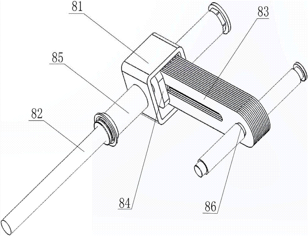
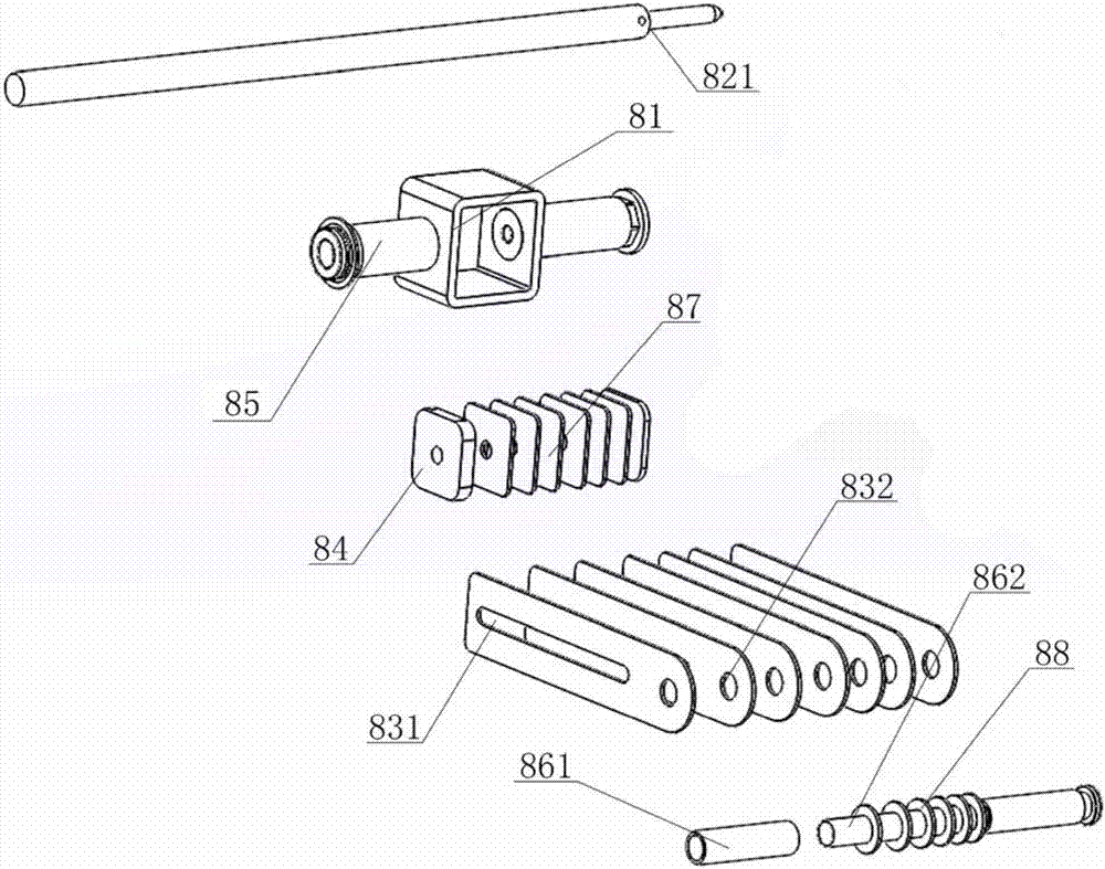
The invention relates to a locking mechanism. The locking mechanism comprises a supporting frame, a locking rod and sliding sheets, the sliding sheets are inserted to the supporting frame, the locking rod penetrates through the sidewall of the supporting frame, the locking rod is in threaded connection with the supporting frame, and the sliding sheets are clamped between the locking rod and the inner wall of the supporting frame. The locking rod is screwed to make a locking block on the locking rod and the supporting frame clamp the sliding sheets in order to restrict the sliding of the sliding sheets, and the locking rod is loosened to make the sliding sheets slide along a slide rail on the locking rod in order to complete position adjustment. Folding extrusion in locking devices in the prior art is improved to threaded rotary extrusion, so the problems of easy wearing, locking failure and short life are solved.

Description

technical field [0001] The invention relates to a chair tray structure, in particular to a locking mechanism. Background technique [0002] As an indispensable tool for home life and office environment, chairs not only have higher and higher comfort requirements when using chairs in home life, but even the office environment has an impact on the comfort and operability of chairs under the premise of work efficiency. Obvious improvement requirements. At present, the back of the general chair has a tilting function and can lock the back of the chair at a specific position. However, the locking mechanism of the existing chair generally has a short service life, is easy to wear, and is likely to cause locking failure. . [0003] For example, the Chinese invention patent (patent number: ZL2013100873272, patent name: a reclining chair tray structure) discloses a locking structure, which realizes that the sliding plate is clamped within a limit by making the corresponding working ...

Claims


Application Information

Patent Timeline
IPC IPC(8): A47C1/027
CPCA47C1/0246A47C1/027
Inventor 王郑兴王星梁彦伟
Owner HENGLIN HOME FURNISHINGS CO LTD
Learn More