Fire pump lifting equipment

A technology of water pump and equipment, applied in the field of fire pump hoisting equipment, can solve problems such as inconvenient transportation

Inactive Publication Date: 2017-07-25
石媛瑗
View PDF0 Cites 4 Cited by
  • Summary
  • Abstract
  • Description
  • Claims
  • Application Information

AI Technical Summary

Problems solved by technology

[0005] In order to overcome the shortcomings of inconvenient transportation in the prior art, the technical problem to be solved by the present invention is to provide a fire pump lifting device that is convenient for transportation

Method used


Image

  • Fire pump lifting equipment
  • Fire pump lifting equipment
  • Fire pump lifting equipment

Examples


Embodiment 1

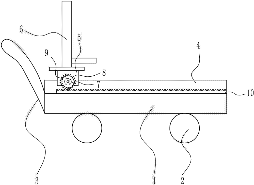
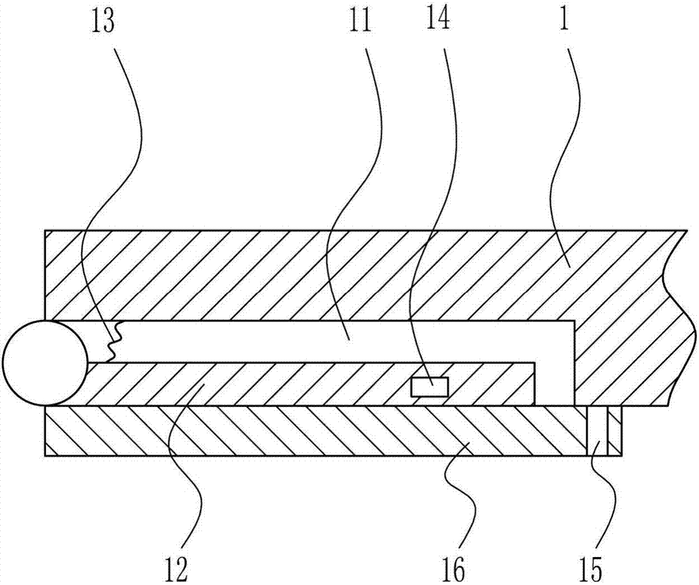
[0027] A fire pump lifting equipment, such as Figure 1-4 As shown, it includes base plate 1, wheel 2, push rod 3, slide rail 4, slider 5, lifting device 6, second motor 7, second rotating shaft 8, gear 9 and rack 10, and the bottom of base plate 1 is arranged symmetrically. There are wheels 2, a push rod 3 is provided on the left side of the base plate 1, a slide rail 4 is provided on the rear side of the top of the base plate 1, and a slide block 5 is slidably connected to the top of the slide rail 4, and a lifting device 6 is provided on the top of the slide block 5, and the slide block 5 The front side is provided with a second motor 7, the output shaft of the second motor 7 is connected with a second rotating shaft 8, the front part of the second rotating shaft 8 is provided with a gear 9, and the front side of the bottom plate 1 top is provided with a rack 10, and the rack 10 and the gear 9 meshes.

Embodiment 2

[0029] A fire pump lifting equipment, such as Figure 1-4 As shown, it includes base plate 1, wheel 2, push rod 3, slide rail 4, slider 5, lifting device 6, second motor 7, second rotating shaft 8, gear 9 and rack 10, and the bottom of base plate 1 is arranged symmetrically. There are wheels 2, a push rod 3 is provided on the left side of the base plate 1, a slide rail 4 is provided on the rear side of the top of the base plate 1, and a slide block 5 is slidably connected to the top of the slide rail 4, and a lifting device 6 is provided on the top of the slide block 5, and the slide block 5 The front side is provided with a second motor 7, the output shaft of the second motor 7 is connected with a second rotating shaft 8, the front part of the second rotating shaft 8 is provided with a gear 9, and the front side of the bottom plate 1 top is provided with a rack 10, and the rack 10 and the gear 9 meshes.

[0030]Lifting device 6 comprises first motor 61, guide rod 62, first r...

Embodiment 3

[0032] A fire pump lifting equipment, such as Figure 1-4 As shown, it includes base plate 1, wheel 2, push rod 3, slide rail 4, slider 5, lifting device 6, second motor 7, second rotating shaft 8, gear 9 and rack 10, and the bottom of base plate 1 is arranged symmetrically. There are wheels 2, a push rod 3 is provided on the left side of the base plate 1, a slide rail 4 is provided on the rear side of the top of the base plate 1, and a slide block 5 is slidably connected to the top of the slide rail 4, and a lifting device 6 is provided on the top of the slide block 5, and the slide block 5 The front side is provided with a second motor 7, the output shaft of the second motor 7 is connected with a second rotating shaft 8, the front part of the second rotating shaft 8 is provided with a gear 9, and the front side of the bottom plate 1 top is provided with a rack 10, and the rack 10 and the gear 9 meshes.

[0033] Lifting device 6 comprises first motor 61, guide rod 62, first ...


PUM


Abstract

The invention relates to a lifting device, in particular to a fire pump lifting device. The technical problem to be solved by the present invention is to provide a fire pump lifting device that is convenient for transportation. In order to solve the above technical problems, the present invention provides such a fire pump lifting equipment, which includes a base plate, wheels, push rods, slide rails, sliders, lifting devices, a second motor, etc.; There is a push rod on the left side, a slide rail on the rear side of the top of the bottom plate, a slide block is slidably connected to the top of the slide rail, a lifting device is provided on the top of the slide block, a second motor is provided on the front side of the slide block, and the output shaft of the second motor A second rotating shaft is connected, a gear is arranged at the front of the second rotating shaft, and a rack is arranged at the front of the bottom plate top. The present invention controls the left and right positions of the fire-fighting water pump through the clockwise rotation of the second motor, and adjusts the height of the fire-fighting water pump through the clockwise rotation of the first motor, which is very simple and fast, and the process is slow.

Description

technical field [0001] The invention relates to a lifting device, in particular to a fire pump lifting device. Background technique [0002] Fire-fighting water pumps refer to special-purpose fire-fighting water pumps or ordinary clean water pumps that meet the national standard "Fire Pump Performance Requirements and Test Methods". It can deliver water to the fire site to extinguish the fire and reduce the damage. The fire-fighting water provided by most fire-fighting water sources needs to be pressurized by fire-fighting water pumps to meet the requirements for water pressure and water volume when extinguishing fires. The failure of the water pump due to improper setting and maintenance will inevitably affect fire fighting and rescue, causing unnecessary losses. The situation of the fire scene is ever-changing, and sometimes it is difficult for the fire pump to find a suitable working position, which affects the rescue of the fire. Therefore, in order to adapt to many d...

Claims


Application Information

Patent Timeline
Patent Type & Authority Applications(China)
IPC IPC(8): B66F7/06B66F7/28
CPCB66F7/0625B66F7/0633B66F7/28
Inventor 石媛瑗
Owner 石媛瑗
Why Eureka
Try Eureka