
equipment for bridge construction

A bridge construction and equipment technology, applied in metal processing equipment, grinding/polishing equipment, manufacturing tools, etc., can solve the problems of automatic isolation of railings, poor polishing accuracy, and high labor intensity of workers, so as to achieve accurate polishing and stability High, improved polishing accuracy, good dust-proof effect

Active Publication Date: 2019-02-15
BEIJING CHANGDAO MUNICIPAL ENG GRP CO LTD
View PDF6 Cites 0 Cited by
  • Summary
  • Abstract
  • Description
  • Claims
  • Application Information

AI Technical Summary

Problems solved by technology

[0002] With the continuous development of urban construction, more and more bridges are being built. Bridges are usually erected on rivers and lakes, so railings must be installed on both sides of the bridge. Railings are essential safety facilities. When the bridge railing is shaped, its surface is usually uneven. , the construction personnel need to polish the railings. Usually, the construction personnel use a hand-held polishing machine for polishing. The labor intensity of the workers is high, time-consuming and laborious. The surface after polishing is uneven, the polishing effect is poor, and the polishing accuracy is poor. The traditional stone processing and polishing process In the process, it is often impossible to effectively isolate the railings automatically, which will cause a large amount of dust and debris splashing on the site, which not only pollutes the environment, but also causes great harm to the personal health of the operators.

Method used


Image

  • equipment for bridge construction
  • equipment for bridge construction
  • equipment for bridge construction

Examples


Embodiment Construction

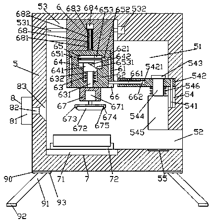
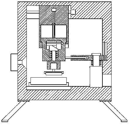
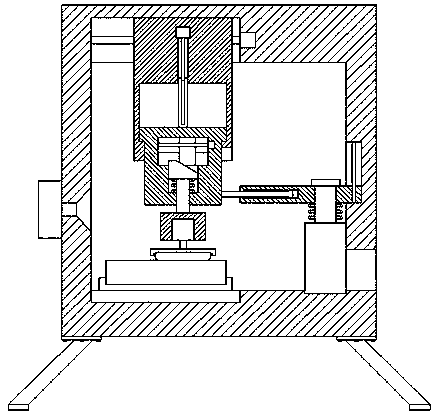
[0025] Such as Figure 1-Figure 5 As shown, a bridge construction equipment of the present invention includes a frame body 5, a polishing chamber 51 is provided inside the frame body 5, and a first sliding groove 53 is provided on the left side of the top of the polishing chamber 51, The right side of the polishing chamber 51 is provided with a second sliding groove 54, and the right side of the frame body 5 below the second sliding groove 54 is provided with an opening 52 whose left end communicates with the polishing chamber 51. The left side of the inner bottom of the polishing chamber 51 is provided with a fastening device 7, and the right side is provided with a sinking groove 55. The first sliding groove 53 is provided with a first helical rod 531 deployed left and right. The screw rod 531 is threadedly connected with a sliding block 6 whose bottom penetrates into the polishing cavity 51. The sliding block 6 is provided with a first sliding cavity 61, and the first slidi...


PUM


Abstract

The invention discloses bridge construction equipment which comprises a frame body, wherein a polishing cavity is formed in the frame body; a first slip groove is formed in the left side of the interior top of the polishing cavity; a second slip groove is formed in the right side of the polishing cavity; an opening end is arranged on the right side of the frame body below the second slip groove, and the left side end of the opening end communicates with the polishing cavity; a connection and fixing device and a sinking groove are arranged on left and right sides of the interior bottom of the polishing cavity; a first heliciform rod is arranged in the first slip groove, and the left and right ends of the first heliciform rod are arranged in an expanded manner; a slip block is in threaded connection with the first heliciform rod, and the bottom of the slip block penetrates into the polishing cavity; a first slip cavity is formed in the slip block; a rise-and-fall slip block is in slip connection with the interior of the first slip cavity; and bulged slip blocks are arranged at the tops of two sides of the rise-and-fall slip block and are in slip connection with interiors of two sides of the first slip cavity. The bridge construction equipment is simple in structure, convenient to operate and high in safety, can automatically control opening and closing of a partition board, and is excellent dustproof effect, accurate in polishing and high in stability.

Description

technical field [0001] The invention relates to the technical field of bridge facilities, in particular to bridge construction equipment. Background technique [0002] With the continuous development of urban construction, more and more bridges are being built. Bridges are usually erected on rivers and lakes, so railings must be installed on both sides of the bridge. Railings are essential safety facilities. When the bridge railing is shaped, its surface is usually uneven. , the construction personnel need to polish the railings. Usually, the construction personnel use a hand-held polishing machine for polishing. The labor intensity of the workers is high, time-consuming and laborious. The surface after polishing is uneven, the polishing effect is poor, and the polishing accuracy is poor. The traditional stone processing and polishing process In the process, it is often impossible to effectively isolate the railings automatically, which will cause a large amount of dust and ...

Claims


Application Information

Patent Timeline
Patent Type & Authority Patents(China)
IPC IPC(8): B24B29/02B24B41/02B24B55/06B24B47/12
CPCB24B29/02B24B41/02B24B47/12B24B55/06
Inventor 方明
Owner BEIJING CHANGDAO MUNICIPAL ENG GRP CO LTD
Learn More