Sinking type air shaft used for underground space building

An underground space and building technology, applied in the ventilation, drainage, safety devices of mines/tunnels, etc., can solve the problems of increased maintenance, damage to high-heeled shoes, high work intensity, etc., and achieves the effect of less maintenance and less wear and tear

Inactive Publication Date: 2017-07-28
CHONGQING REAL ESTATE COLLEGE
View PDF9 Cites 1 Cited by
  • Summary
  • Abstract
  • Description
  • Claims
  • Application Information

AI Technical Summary

Problems solved by technology

Yet this prior art just exists following three deficiencies because of such structure: one, on the wheel and the dirt on people's shoe bottom surface, must fall into its wind shaft cavity by the grid hole of this cover plate 36 301, a little longer time will inevitably block all the gaps in the graded stone layer 38 at the bottom of the wind shaft cavity 301, and then cause the problem that rainwater cannot be drained along its blind drainage ditch 37—this naturally increases. Increased the number of times for maintenance and removal of dirt, and each time the dirt in the 38 gaps of the graded stone layer is removed, the work intensity is still relatively large
Two, the cover plate 36 can only be covered at the opening of the wind shaft cavity 301 in a manner that can be opened at any time
In this prior art, the hole cover plate 36 with a grid is used as a part of the road surface, and the "occasionally happening" thing has become "occurring all the time". Like this, not only the high-heeled shoes will be damaged, but also the lady's ankle will be sprained.

Method used


Image

  • Sinking type air shaft used for underground space building
  • Sinking type air shaft used for underground space building
  • Sinking type air shaft used for underground space building

Examples


Embodiment Construction

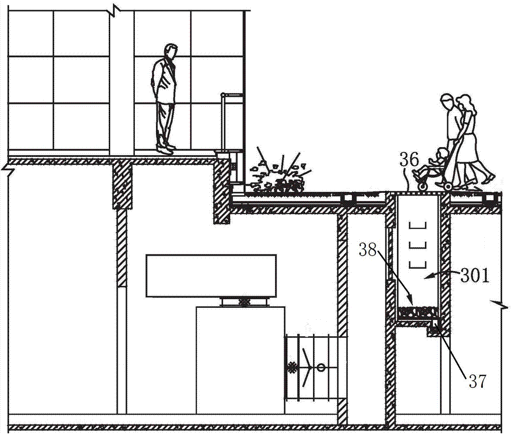
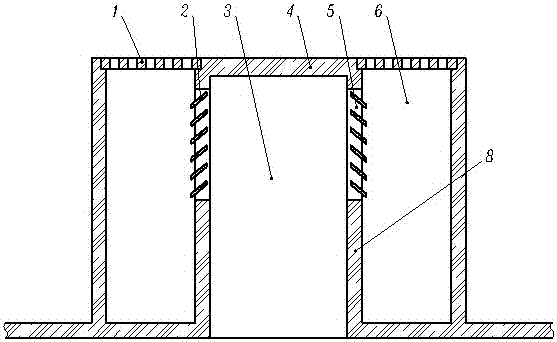
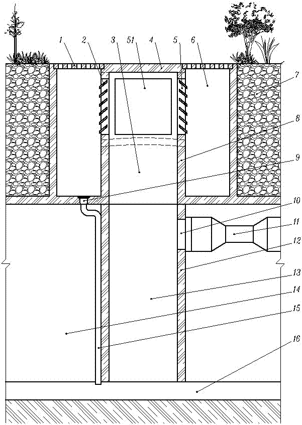
[0015] Sunken air shafts for underground space construction (refer to figure 2 , 3 , 4), the top surface of the sunken air shaft is a section of the outdoor road surface, and the rest is sunk into the ground. In the present invention, under the top surface 4, there are four side wall panels 8 that are fixedly connected with the top surface 4 to form the upper ventilation cavity 3 of the air shaft, and between the two side wall panels 8 parallel to the road There is a roadside drainage ditch 6 covered with a water grate 1 on the outside parallel to the road; the upper part of these two side wall panels 8 has a wind guide window 5 communicating with the roadside drainage ditch 6 and the upper ventilation cavity 3; The bottom of the ventilation cavity 3 finally communicates with the exhaust fan 11 in the underground space building 14 .

[0016] As disclosed so far, those skilled in the art combined with their understanding of the beneficial effects of the present invention wil...


PUM


Abstract

The invention provides a sinking type air shaft used for an underground space building. The top surface of the sinking type air shaft is a section of the outdoor road surface, and other parts of the outdoor road surface are all sunk into the ground. In the sinking type air shaft used for the underground space building, the position below the top surface is fixedly connected with the top surface to form four side wall plates of an air shaft upper ventilating cavity, roadside drainage ditches covered with water perforated strainers and parallel to the positions above a road are formed in the outer sides of two side wall plates parallel to the road, and air guiding windows communicating with the roadside drainage ditches and the upper ventilating cavity are formed in the upper portions of the two side wall plates; and the lower portion of the upper ventilating cavity finally communicates with an air and smoke discharging draught fan in the underground space building. The sinking type air shaft used for the underground space building has the advantages that the number of times of maintenance is extremely few, and walking is smooth and safe when pedestrians walk on the air shaft, and driving is smooth and safe when vehicles are driven on the air shaft. The sinking type air shaft is applicable to building of sinking type air shafts of various underground buildings which need ventilating such as underground stores and underground warehouses.

Description

technical field [0001] The invention relates to an air shaft for ventilating underground space buildings, especially an air shaft whose top surface is flush with the road surface. Background technique [0002] In order to save construction land, many garages, some shopping malls, warehouses, etc. are built under buildings, green spaces and roads to form underground space buildings. The air quality has reached the corresponding standard. At present, since the air outlets on the upper part of the air shaft are all higher than the ground, some green land and / or other grounds will be occupied for construction. From the point of view of saving construction land, it is obviously regrettable; in addition, the upper part of the wind shaft above the ground also somewhat damages the landscape of office buildings and / or residential quarters. Therefore, in order to overcome these defects, the invention patent with the authorized announcement number CN104563449B and the name "Landscape...

Claims


Application Information

Patent Timeline
Patent Type & Authority Applications(China)
IPC IPC(8): E21F1/00E21F16/00E21F17/103
CPCE21F1/00E21F16/00E21F17/103
Inventor 张青山刘娜娜王雪琴刘清秀陈爽
Owner CHONGQING REAL ESTATE COLLEGE
Why Eureka
Try Eureka