
Computer

A computer, power-on time technology, applied in electrical control, fuel injection control, engine control, etc., to reduce fuel consumption, prolong service life, and improve low-speed torque.

Inactive Publication Date: 2017-07-28
林培青
View PDF0 Cites 0 Cited by
  • Summary
  • Abstract
  • Description
  • Claims
  • Application Information

AI Technical Summary

Problems solved by technology

[0007] The invention proposes a computer, which solves the problem of uniform compression ratio and fuel injection time of different engine loads in the prior art

Method used


Image

  • Computer
  • Computer
  • Computer

Examples


Embodiment Construction

[0056] The following will clearly and completely describe the technical solutions in the embodiments of the present invention with reference to the accompanying drawings in the embodiments of the present invention. Obviously, the described embodiments are only some, not all, embodiments of the present invention. Based on the embodiments of the present invention, all other embodiments obtained by persons of ordinary skill in the art without creative efforts fall within the protection scope of the present invention.

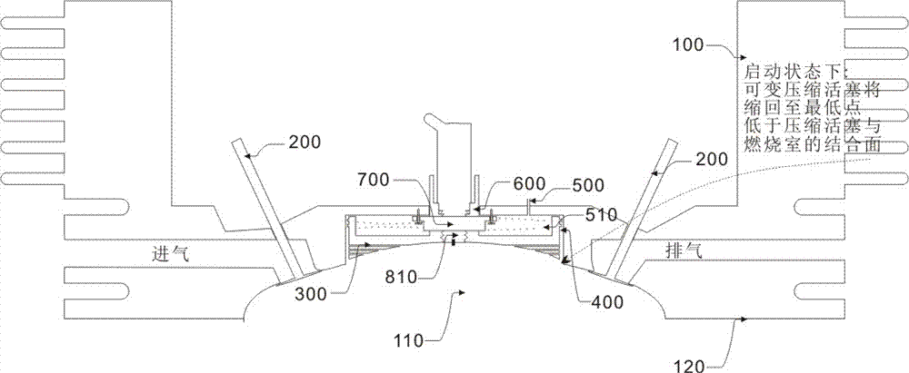
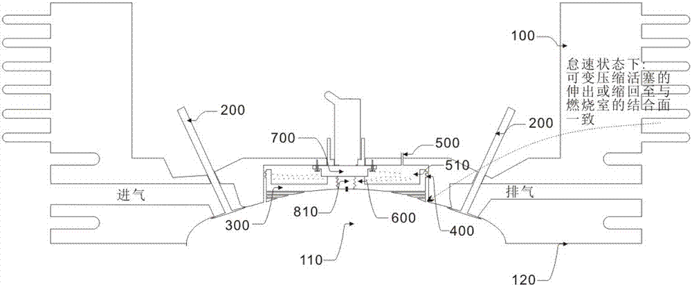
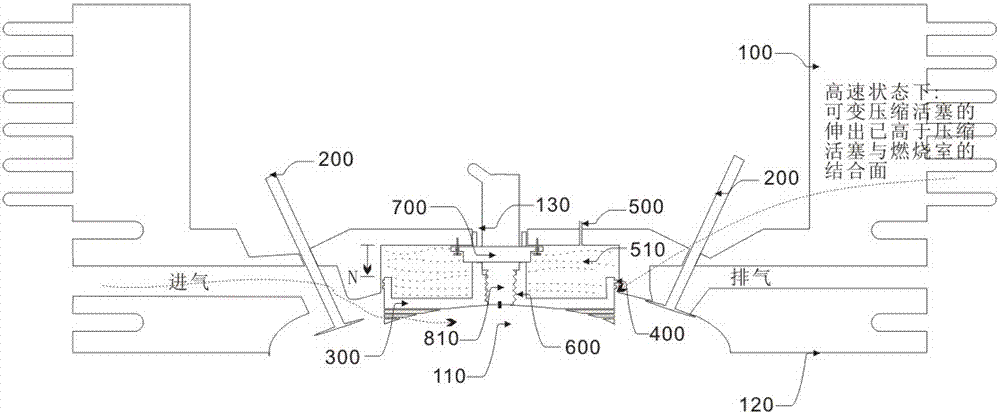
[0057] An engine with electronically controlled variable compression ratio and fuel injection position, which includes a variable compression ratio mechanism capable of changing the mechanical compression ratio, and a fuel injection nozzle 810 that works synchronously with the telescoping mechanism, and makes the engine run at low load The compression ratio of the engine is completely different from the compression ratio and fuel injection position when the engine i...


PUM


Abstract

The present invention proposes a computer, which includes a fuel injector and an engine connected to the fuel injector; the computer is connected to a sensor, and the computer adjusts the fuel injection time of the fuel injector based on the load of the engine. The fuel injection time is not to increase or decrease the energization time of the fuel injectors, but to adjust the fuel injection in advance or backward when the fuel injection time remains unchanged. The backward fuel injection is based on the momentary excessive load of the engine and the advance fuel injection is based on the lightening of the engine load, thereby increasing the power and power of the engine.

Description

technical field [0001] The invention relates to a gasoline engine, in particular to an engine control computer capable of changing the compression ratio according to the engine load and rotation speed. Background technique [0002] The compression ratio of the engine refers to the ratio of the stroke of the working piston in the cylinder to the combustion chamber. The higher the compression ratio, the better the combustion efficiency. However, the higher the compression ratio, the higher the knocking of the engine, and the easier it is for the cylinder and piston to knock and wear. Especially under high load conditions, the power of the engine will drop instead. [0003] As the grade of gasoline gets higher and higher, the increase of octane number is to reduce the knocking caused by the high compression ratio. However, its effect is limited. It can only be controlled at 13:1. Of course, due to the refining and manufacturing process of gasoline in the same region, the comp...

Claims


Application Information

Patent Timeline
IPC IPC(8): F02D41/30F02D15/00
CPCF02D41/30F02D15/00
Inventor 林培青
Owner 林培青
Learn More