Correction triggering method of micro-projection equipment and micro-projection equipment
A kind of equipment and technology of micro-projection, which is applied in the parts of color TV, using projection device image reproducer, electrical components, etc., can solve high-frequency noise, excessive sound of micro-projection equipment, and frequent triggering of auto-focus by micro-projection equipment or picture automatic correction and other issues, to achieve the effect of improving accuracy, ensuring normal use, and solving the problems of frequent triggering of auto focus or automatic picture correction
- Summary
- Abstract
- Description
- Claims
- Application Information
AI Technical Summary
Problems solved by technology
Method used
Image
Examples
Embodiment 1
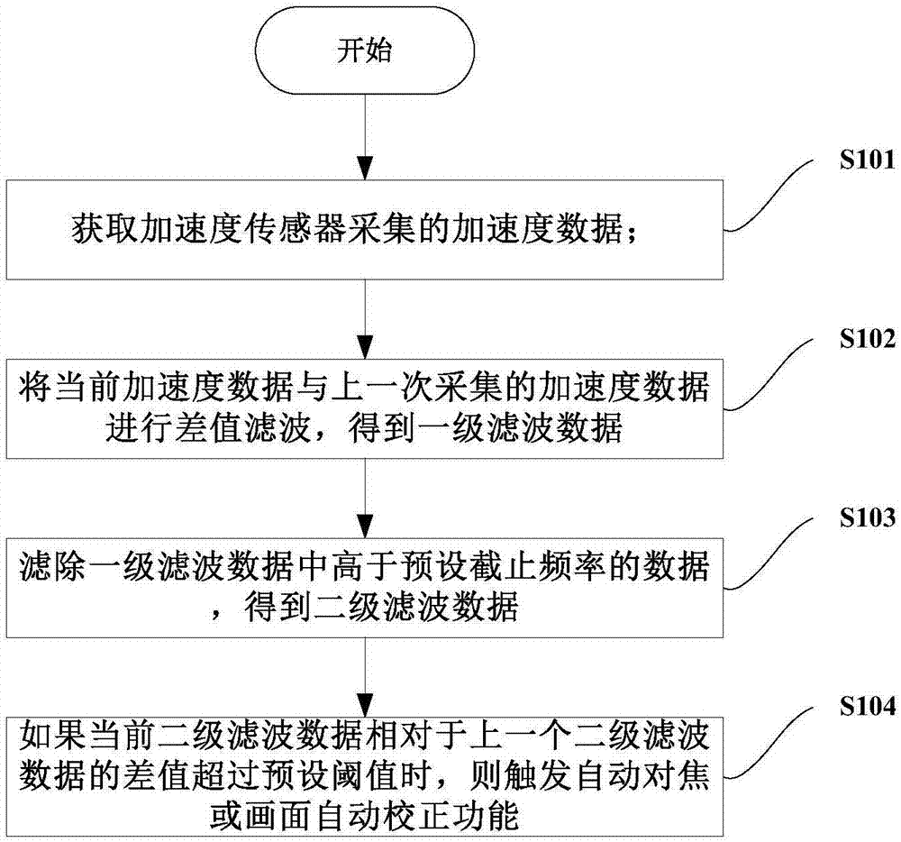
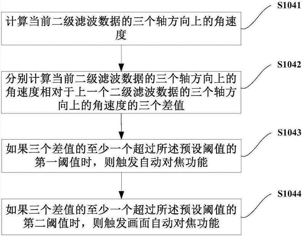
[0032] The embodiment of the present application discloses a calibration triggering method and device for micro-projection equipment, see figure 2 , is a schematic flow chart of Embodiment 1 provided in this application.
[0033] In step S101, the acceleration data collected by the acceleration sensor is acquired.
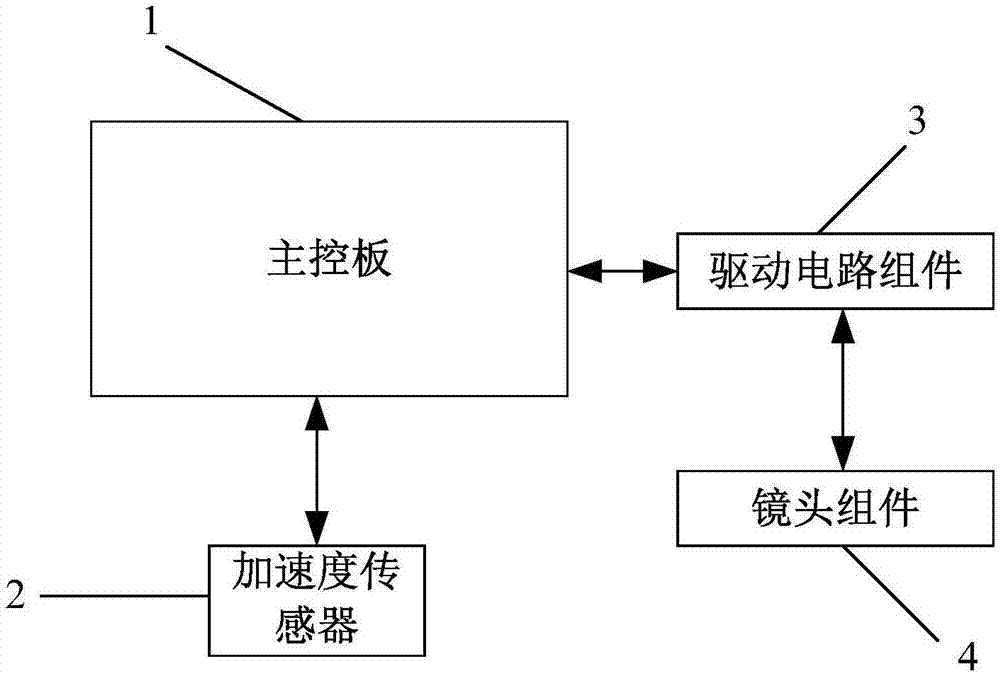
[0034] An acceleration sensor or a digital acceleration sensor is installed in the micro-projection device. When the micro-projection device moves, the main chip obtains the acceleration data collected by the acceleration sensor. The acceleration data here refers to the original acceleration data collected by the acceleration sensor. When the micro-projection device is displaced, the acceleration sensor can sense the displacement of the micro-projection device and the direction in which the micro-projection device is displaced.
[0035] In step S102, the difference filtering is performed on the current acceleration data and the acceleration data collected last ti...
Embodiment 2
[0057] see Figure 4 , is a schematic flow chart of Embodiment 2 provided by the present application.
[0058] In step S201, the acceleration data collected by the acceleration sensor is acquired.
[0059] In step S202, the difference filtering is performed on the current acceleration data and the acceleration data collected last time to obtain first-level filtered data.
[0060] In step S203, data higher than a preset cut-off frequency in the primary filtering data is filtered out to obtain secondary filtering data.
[0061] In step S204, if the rate of change of the current secondary filtering data relative to the previous secondary filtering data exceeds a preset rate of change, an auto-focus or image auto-correction function is triggered.
[0062] After filtering out the data higher than the preset cut-off frequency in the filtered data, the secondary filtered data is obtained. As can be seen from the above-mentioned embodiment, it is determined whether the micro-projec...
Embodiment 3
[0073] see Image 6 , is a schematic flowchart of Embodiment 3 provided in the embodiment of this application.
[0074] In step S301, the acceleration data collected by the acceleration sensor is acquired.
[0075] In step S302, three differences between the acceleration data in the three axis directions acquired at the current moment and the acceleration data in the three axis directions corresponding to the previous moment are calculated.
[0076] In step S303, when at least one of the three differences is greater than the preset difference, the acceleration data in the three axis directions acquired at the current moment is deleted to obtain primary filtering data.
[0077] Calculate the three differences between the acceleration data in the three axis directions at the current moment and the acceleration data in the three axis directions corresponding to the previous moment. If any of the three differences is greater than the preset difference, it means The acceleration ...
PUM
 Abstract
Description
Claims
Application Information
 - R&D
- Intellectual Property
- Life Sciences
- Materials
- Tech Scout
- Unparalleled Data Quality
- Higher Quality Content
- 60% Fewer Hallucinations
Browse by: Latest US Patents, China's latest patents, Technical Efficacy Thesaurus, Application Domain, Technology Topic, Popular Technical Reports.
© 2025 PatSnap. All rights reserved.Legal|Privacy policy|Modern Slavery Act Transparency Statement|Sitemap|About US| Contact US: help@patsnap.com


