Intelligent shoe cabinet

A shoe cabinet and intelligent technology, applied in wardrobes, cupboards, sanitary equipment for toilets, etc., can solve problems such as easy to get athlete's foot, poor user experience, and affect the user's health, so as to avoid athlete's foot and improve user experience. Comfortable and efficient use of the effect

Inactive Publication Date: 2017-08-01
FUZHOU PINXING TECH DEV
View PDF5 Cites 6 Cited by
  • Summary
  • Abstract
  • Description
  • Claims
  • Application Information

AI Technical Summary

Problems solved by technology

When opening the cabinet door to take the shoes, the smell is strong and the user experience is very b

Method used


Image

  • Intelligent shoe cabinet
  • Intelligent shoe cabinet

Examples


Embodiment 1

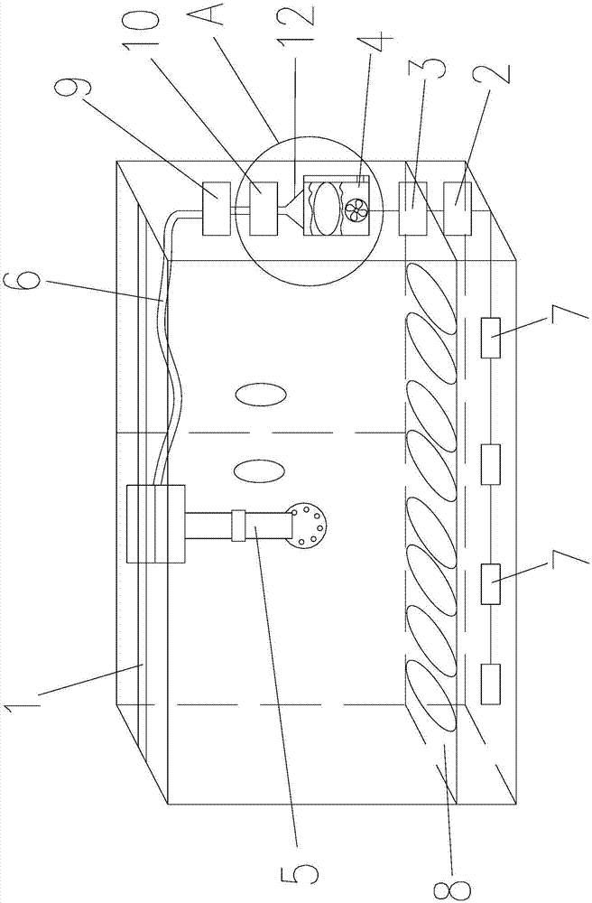
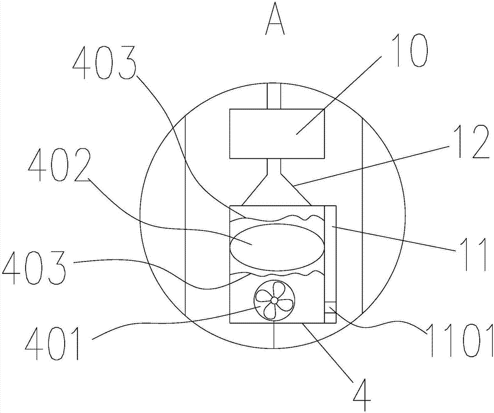
[0024] Such as Figure 1-2 The shown embodiment one of an intelligent shoe cabinet of the present invention includes a cabinet chamber, and a guide rail 1, a controller 2, a power supply 3 and a bellows 4 are arranged in the cabinet chamber, and an air injection device 5 is slidably connected to the guide rail 1; A fan 401 is installed in the bellows 4, and an air outlet is provided on the wall of the bellows 4 opposite to the outlet surface of the fan 401. An atomizing sheet 402 and a mesh cloth 403 coated with a bactericide are arranged between the fan 401 and the air outlet. , the air outlet communicates with the air inlet of the jet device 5 through the flexible pipe 6; several pressure sensors 7 are embedded on the shoe-putting plate in the cabinet chamber, and the output end of the pressure sensor 7 is connected to the signal input end of the controller 2 to control The signal output end of the device 2 is used to control the switch of the power supply 3, and the power s...

Embodiment 2

[0033] The difference between Embodiment 2 and Embodiment 1 of an intelligent shoe cabinet of the present invention is that the shoe boards in the chamber of the cabinet are arranged in multiple layers, and the cavity between two adjacent layers of shoe boards constitutes a space for placing shoes. Layer cavity; guide rail 1 is vertically installed in the cabinet chamber; on the sliding track of air injection device 5, the air outlet of air injection device 5 is towards the inlet of each layer cavity. The other structures of this embodiment are the same as those of Embodiment 1.

[0034] The cabinet chamber of the present embodiment is composed of a plurality of layer cavities, which makes full use of the internal space of the cabinet chamber and is convenient for placing more shoes, and the vertically sliding air jet device 5 can automatically intelligently control the shoes in each layer cavity. Sterilization is carried out efficiently, and the effective utilization rate of ...


PUM


Abstract

The invention belongs to the field of intelligent furniture, and particularly relates to an intelligent shoe cabinet which comprises a cabinet chamber. A guide rail, a controller, a power source and an air box are arranged in the cabinet chamber, and an air injection device is slidably connected into the guide rail; a fan is mounted in the air box, an air outlet is formed in the wall of the air box and is opposite to an air outlet surface of the fan, an atomizing film and screen cloth are arranged between the fan and the air outlet, bactericides are coated on the screen cloth, and the air outlet is communicated with the air injection device via a hose; a plurality of pressure sensors are embedded in a shoe accommodating plate of the cabinet chamber, output ends of the pressure sensors are connected with an input end of the controller, an output end of the controller is used for controlling a switch of the power source, and the power source is used for driving the fan and the atomizing film to work and driving the air injection device to slide on the guide rail back and forth. The intelligent shoe cabinet has the advantages that shoes in the cabinet chamber can be automatically intelligently sterilized and disinfected, peculiar smell of the shoes can be automatically intelligently removed, air is fresh, and comfortable experience can be brought to users; beriberi can prevented after the users wear the shoes, and accordingly the intelligent shoe cabinet is favorable for the physical health of the users.

Description

technical field [0001] The invention belongs to the field of intelligent furniture, and in particular relates to an intelligent shoe cabinet. Background technique [0002] In life, if the shoes are worn for a long time, microorganisms such as bacteria and fungi are prone to breed in the shoes, resulting in odor and even mildew. When opening the cabinet door to take the shoes, the smell is strong and the user experience is very bad; and after wearing the shoes, it is easy to get athlete's foot, which affects the health of the user. Contents of the invention [0003] The purpose of the present invention is to overcome the defects of the prior art, and provide a shoe that can automatically and intelligently sterilize and deodorize the shoes in the cabinet cavity, the air is fresh, and the user experience is very comfortable; after wearing the shoes, it can avoid staining Athlete's foot is a smart shoe cabinet that is beneficial to the user's health. [0004] The technical s...

Claims


Application Information

Patent Timeline
IPC IPC(8): A47B61/04A61L2/20A61L2/04A61L2/24A61L2/22A61L101/10
CPCA61L2/04A61L2/20A61L2/202A61L2/22A61L2/24A47B61/04
Inventor 陈伟高灿辉
Owner FUZHOU PINXING TECH DEV
Why Eureka
Try Eureka