Check patentability & draft patents in minutes with Patsnap Eureka AI!

Air flow distribution plate for fluidized bed

A gas flow distribution plate, fluidized bed technology, applied in chemical/physical processes, chemical instruments and methods, etc., can solve problems such as disturbing gas flow stability

Inactive Publication Date: 2017-08-01
厦门朋鹭金属工业有限公司
View PDF6 Cites 6 Cited by
  • Summary
  • Abstract
  • Description
  • Claims
  • Application Information

AI Technical Summary

Problems solved by technology

This method can use shear stress to disperse the agglomerates because the direction of stirring is perpendicular to the direction of airflow, but this method will greatly interfere with the stability of airflow

Method used


Image

  • Air flow distribution plate for fluidized bed
  • Air flow distribution plate for fluidized bed
  • Air flow distribution plate for fluidized bed

Examples


Embodiment 1

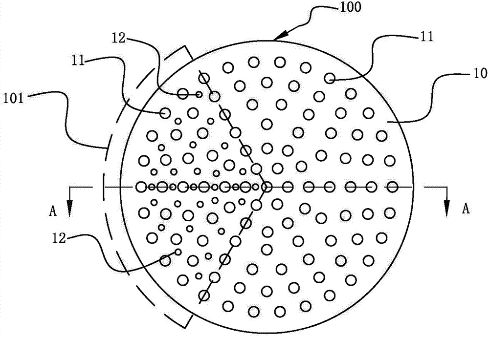
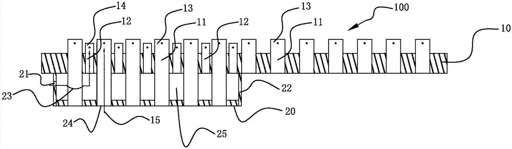
[0026] Please refer to figure 1 and figure 2 , the air flow distribution plate 100 for the fluidized bed of the present embodiment comprises a first base plate 10 and a second base plate 20, the second base plate 20 is arranged below the first base plate 10 in parallel, and the interval between the second base plate 20 and the first base plate 10 A cavity 25 is formed closed by the side wall 22 . The area of ​​the second substrate 20 is equal to the area of ​​the first substrate 10 , preferably, the area of ​​the second substrate 20 is smaller than the area of ​​the first substrate 10 .

[0027] The first base plate 10 is evenly distributed with many primary air passage holes 11 for maintaining the suspension of material particles and at least one secondary air passage hole 12 for blowing away the accumulated material agglomerated particles, and the outlet of the primary air passage hole 11 is provided with a A wind cap 13 and a secondary air cap 14 are provided at the outl...

Embodiment 2

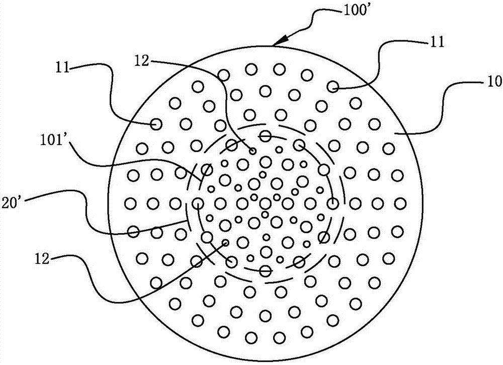
[0042] Please refer to image 3 The difference between the second embodiment and the first embodiment is that the stacking area 101' of the air distribution plate 100' for the fluidized bed is a circular area in the center, and the second substrate 20' corresponds to the stacking area 101' The second substrate 20 ′ is parallel to the bottom of the first substrate 10 , and the area of ​​the second substrate 20 ′ is smaller than that of the first substrate 10 . In the second embodiment, the area where the material agglomerated particles of the air flow distribution plate 100' of the fluidized bed is easy to accumulate is mainly distributed in the central area, and the accumulation area 101' in the central area is set to blow off the accumulated material agglomeration The secondary air through holes 12 of the particles, and the opening ratio of the secondary air 23 of the first substrate 10 is smaller than the opening ratio of the primary air 15, so that the wind speed of the sec...


PUM


Abstract

The invention discloses an air flow distribution plate for a fluidized bed. The air flow distribution plate consists of a first base plate, wherein a plurality of primary air through holes for maintaining material particles to be suspended, wind caps matched with the primary air through holes, at least one secondary air through hole for blowing away agglomerated particles among the material particles and wind caps matched with the secondary air through holes are uniformly distributed in the first base plate; the secondary air through holes are arranged adjacently to the primary air through holes; air speed of secondary air passing through the secondary air through holes is greater than that of primary air passing through the primary air through holes, and channels for providing the primary air for the primary air through holes and channels for providing secondary air for the secondary air through holes are mutually independent. The air flow distribution plate has the advantages that the accumulation of material agglomerated particles is reduced, and the interference to the working air flow stability of the fluidized bed is also reduced.

Description

technical field [0001] The invention relates to an air flow distribution plate, in particular to an air flow distribution plate for a fluidized bed. Background technique [0002] As an efficient production method, fluidization method is widely used in chemical industry, metallurgy, medicine and other industries. The boiling layer is one of the important forms of fluidization technology, which uses the suspension state of solid particles in the fluid to complete a series of physical and chemical changes. The distribution plate is a key part of the fluidized bed (fluidized bed), and it has two main functions: (1) to support the material, so that the material will not fall in a fixed area when the speed is less than the limit; (2) to evenly distribute the air flow, so that The airflow is evenly distributed throughout the container. Generally, the air flow opening ratio of the air flow distribution plate of the fluidized bed is generally between 0.5% and 1.5%. When the openin...

Claims


Application Information

Patent Timeline
IPC IPC(8): B01J8/24
CPCB01J8/24B01J8/1818
Inventor 林高安陈杉杉龙本夫吴冲浒吴其山黄华傅国富
Owner 厦门朋鹭金属工业有限公司
Features
  • R&D
  • Intellectual Property
  • Life Sciences
  • Materials
  • Tech Scout
  • Unparalleled Data Quality
  • Higher Quality Content
  • 60% Fewer Hallucinations
Learn More