
Pneumatic tire

A technology for pneumatic tires and treads, which is applied to the reinforcement layers, tire parts, tires, etc. of pneumatic tires, can solve the problems of not yet established convex edges and concave edges, rising manufacturing costs, etc., so as to prevent the generation of convex edges and concave edges. The effect of suppressing the increase in manufacturing cost

Inactive Publication Date: 2017-08-08
SUMITOMO RUBBER IND LTD
View PDF7 Cites 0 Cited by
  • Summary
  • Abstract
  • Description
  • Claims
  • Application Information

AI Technical Summary

Problems solved by technology

Such a fee would incur an increase in manufacturing costs
[0017] In this way, various studies have been made to prevent the occurrence of convex and concave edges, but the current situation is that a technology that can sufficiently and inexpensively prevent the occurrence of convex and concave edges has not been established.

Method used


Image

  • Pneumatic tire
  • Pneumatic tire
  • Pneumatic tire

Examples


Embodiment 1

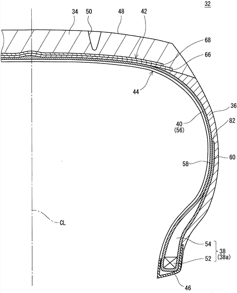
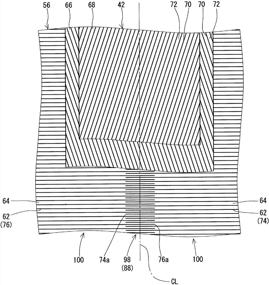
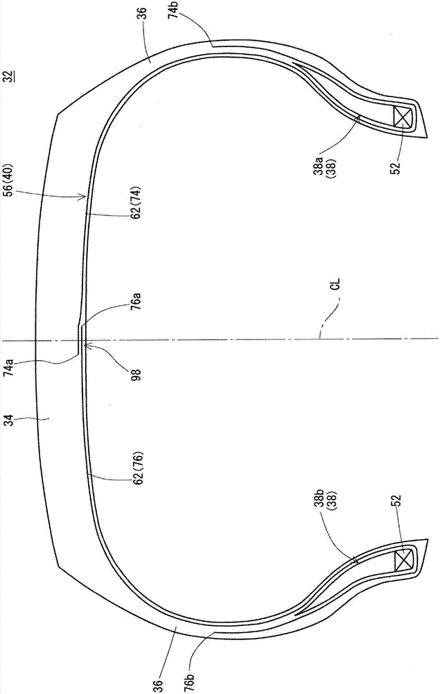
[0103] make Figure 1-3 tires shown. The size of this tire is 155 / 65R13. In the production of this tire, the first sheet and the second sheet are used to form a sheet-shaped carcass ply. The width AL of the longitudinal joint portion in this carcass ply was 10 mm. In this carcass ply, the leading edge and the trailing edge are formed to extend in the width direction without being inclined with respect to the width direction. This is noted as "Width" in the column of processing of the edge.

Embodiment 2-7

[0109] The width AL of the longitudinal joint portion was as shown in Table 1 below, and the other was the same as that of Example 1, thereby producing tires of Examples 2-7.


PUM

PropertyMeasurementUnit
widthaaaaaaaaaa
lengthaaaaaaaaaa

Abstract

To provide a pneumatic tire (32) that prevents sufficiently occurrence of a bulge and a dent while suppressing increase in manufacturing costs. A carcass (40) of a tire (32) is hung between a first bead (38a) and a second bead (38b) along the inside of a tread (34) and a side wall (36). The carcass (40) comprises a carcass ply (56). The carcass ply (56) includes many carcass cords (62). The carcass cords (62) include many first cords (74) arranged parallely in a circumference direction and many second cords (76) arranged parallely in the circumference direction. Each of the first cords (74) extends from a first tip (74a) thereof toward the first bead (38a). Each of the second cords (76) extends from a second tip (76a) thereof toward the second bead (38b). The part of the second tip (76a) overlaps with the part of the first tip (74a).

Description

technical field [0001] The present invention relates to pneumatic tires. Background technique [0002] The tire has a carcass. The carcass has a carcass ply. The carcass ply includes a plurality of cords arranged side by side. [0003] Image 6 It is a sectional view showing a part of a conventional tire 2 . in the Image 6 In , the case of the cord 6 contained in the carcass 4 is shown. in the Image 6 , the dotted line CL represents the equatorial plane of the tire 2 . [0004] The carcass ply 8 is stretched between the beads 10 on both sides and along the tread 12 and the sidewall portion 14 . like Image 6 As shown, the cords 6 of the carcass ply 8 are also spanned between the beads 10 on both sides, along the tread 12 and the sidewall portion 14 . [0005] In forming the carcass ply 8, a sheet is prepared. The sheet is composed of a plurality of cords 6 juxtaposed and a topping rubber. In forming the carcass ply 8 , one edge portion of the sheet overlaps and joi...

Claims


Application Information

Patent Timeline
Patent Type & Authority Applications(China)
IPC IPC(8): B60C9/04B29D30/30
CPCB29D30/30B60C9/04
Inventor 冲康弘
Owner SUMITOMO RUBBER IND LTD
Learn More