
Driving circuit and display device

A technology for driving circuits and display devices, which is applied to static indicators, instruments, etc., can solve the problems of delicate images, beautiful appearance, and the level needs to be improved, and achieve the effect of increasing the number of colors and delicate images.

Active Publication Date: 2017-08-08
WUHAN CHINA STAR OPTOELECTRONICS TECH CO LTD
View PDF9 Cites 0 Cited by
  • Summary
  • Abstract
  • Description
  • Claims
  • Application Information

AI Technical Summary

Problems solved by technology

The display colors of the existing reflective display devices are 64 colors, and the number of displayed colors is small, so the displayed images need to be improved in terms of fineness, beauty and level

Method used


Image

  • Driving circuit and display device
  • Driving circuit and display device
  • Driving circuit and display device

Examples


Embodiment Construction

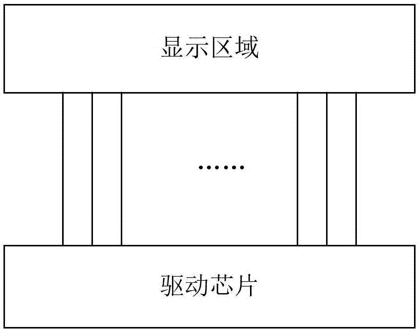
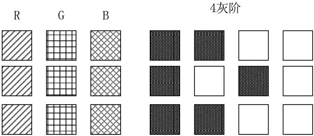
[0014] See figure 1 , Is the circuit diagram of the existing drive circuit. From figure 1 It can be seen that the drive chip is connected to the display area and is used to output drive signals to the display area for image display. See figure 2 , Is the schematic diagram of the existing area color scale method. From figure 2 It can be seen that each pixel in the display area includes three sub-pixels (ie, red sub-pixel R, green sub-pixel G, and blue sub-pixel B), where each sub-pixel is divided into three parts, and each part has only The two states of light and dark, thus forming 4 gray scales, a pixel formed by three sub-pixels displays 64 colors. Because the number of display colors is limited, the displayed image needs to be improved in fineness, beauty and level.

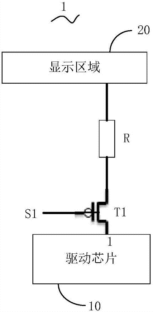
[0015] Please refer to image 3 , Is a schematic circuit diagram of the first embodiment of the driving circuit of the present invention. The driving circuit 1 includes a driving chip 10, a first controllable...


PUM


Abstract

The invention discloses a driving circuit and a display device. The driving circuit comprises a driving chip, a first controllable switch and a resistor. The first pin of the driving chip is connected with the second end of the first controllable switch. The control end of the first controllable switch receives a switching signal. The first end of the first controllable switch is connected with a display area through the resistor. When the driving circuit is in a resistor voltage-dividing operating mode, the switching signal is a low-level signal, the first controllable switch is switched on, the resistor divides voltage, and the display area displays a first type of color in order to increase the number of displayed colors and further to make a displayed image fine, beautiful and stratified.

Description

Technical field [0001] The present invention relates to the field of display technology, in particular to a driving circuit and a display device. Background technique [0002] With the development of display technology, display devices have been widely used in various fields, such as various electronic products such as mobile phones, tablet computers, or electronic paper. A typical reflective display device includes red, green, and blue color filters and a reflective display layer. The reflective display layer is located under the color filters to selectively reflect light passing through the color filters, so that the reflective display device displays images. The display color of the existing reflective display device is 64 colors, and the number of display colors is small. Therefore, the displayed image needs to be improved in terms of fineness, beauty, and level. Summary of the invention [0003] The main technical problem solved by the present invention is to provide a driv...

Claims


Application Information

Patent Timeline
Patent Type & Authority Applications(China)
IPC IPC(8): G09G3/20
CPCG09G3/2003
Inventor 宋文庆
Owner WUHAN CHINA STAR OPTOELECTRONICS TECH CO LTD
Learn More