Three-dimensional modeling apparatus and manufacturing method

a three-dimensional modeling and manufacturing method technology, applied in the field of three-dimensional modeling apparatus, can solve problems such as color reproducibility degradation

Active Publication Date: 2018-04-03
SEIKO EPSON CORP
View PDF14 Cites 0 Cited by
  • Summary
  • Abstract
  • Description
  • Claims
  • Application Information

AI Technical Summary

Benefits of technology

[0009]With the three-dimensional modeling apparatus of such a mode, the object is also colored in the depth direction thereof, whereby, color density observed from outside of the object can be more finely expressed. Therefore, the number of colors that can be expressed per unit area on the surface of the object can be increased, and color reproducibility can also be improved.
[0011]With the three-dimensional modeling apparatus of such a mode, it is possible to adjust the amount of colored liquid to be discharged into the sub unit grille that is a unit finer than a unit grille that is in accordance with the modeling resolution, and it is possible to improve color reproducibility when modeling a colored three-dimensional object. In addition, in the above mode, in the case where the spatial volume of the sub unit grille is not filled with the amount of colored liquid discharged into the sub unit grille, the remaining spatial volume of the sub unit grille is filled with colorless liquid. Therefore, the volumes of the sub unit grilles are uniformized, and the volumes of the unit grilles are also uniformized. Therefore, the three-dimensional object can be accurately modeled.
[0013]With the three-dimensional modeling apparatus of this mode, after the first sub unit grille is filled with liquid discharged from the first nozzle group and the second nozzle group, the second sub unit grille can be filled with liquid discharged from the third nozzle group and the fourth nozzle group. Therefore, the spatial volume of each of the sub unit grilles can be filled with colorless liquid while adjusting the amount of colored liquid discharged into each of the first sub unit grille and second sub unit grille. Thereby, the volumes of the sub unit grilles can be more easily uniformized. In addition, because colored liquid discharged into the first sub unit grille is positioned in the lower portion of the first sub unit grille, and colorless liquid is positioned in the upper portion of the first sub unit grille, color reproducibility can be improved in the case where the lower side of the first sub unit grille is the surface side of the object.
[0015]With the three-dimensional modeling apparatus of such a mode, for example, even in the case where the total amount of the colored liquid discharged from the fifth nozzle group is small, and the amount of colorless liquid necessary for filling the unit grille with liquid is greater than the amount that can be discharged from either the sixth nozzle group or the seventh nozzle group, it is possible to fill the unit grille with liquid by discharging the colorless liquid sequentially from the two nozzle groups, that is, the sixth nozzle group and the seventh nozzle group. Therefore, the volumes of the unit grilles can be more easily uniformized.
[0017]With the three-dimensional modeling apparatus of such a mode, the way that colored liquid discharged into a unit grille spreads in the unit grille can be uniformized, and color variation for each of the unit grilles can be reduced. In other words, the colored liquid discharged into the unit grille spreads differently after landing in the case of landing on colored liquid and in the case of landing on colorless liquid. Therefore, if the top portion of the unit grille is constituted by colorless liquid, it is possible to cause the colored liquid that is discharged into a unit grille above this unit grille to land on the colorless liquid. Accordingly, it is possible to uniformize the way that the colored liquid spreads after landing, and color variation due to the difference in way of spreading can be reduced.

Problems solved by technology

However, with the technique described in JP-A-2011-73163, only one color can be expressed for each layer, and therefore there is a problem in that, when observed from outside, color reproducibility deteriorates.

Method used


Image

  • Three-dimensional modeling apparatus and manufacturing method
  • Three-dimensional modeling apparatus and manufacturing method
  • Three-dimensional modeling apparatus and manufacturing method

Examples


first embodiment

A. First Embodiment

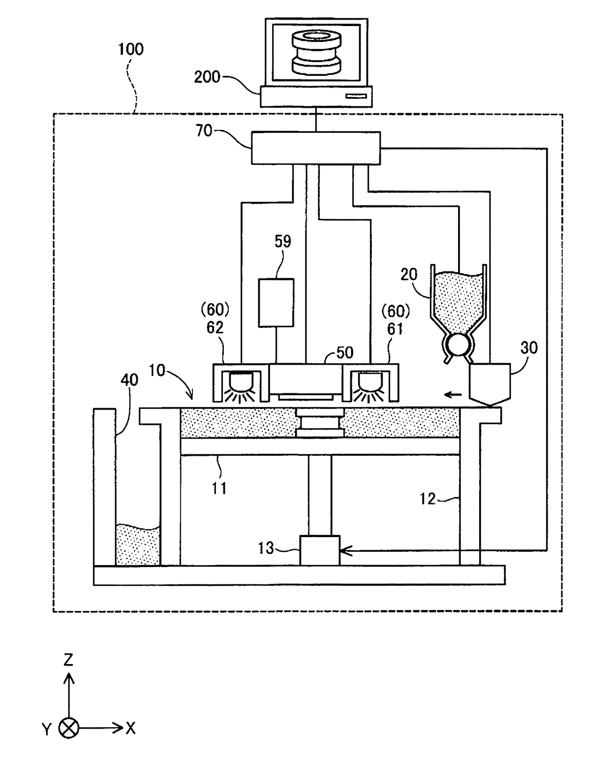
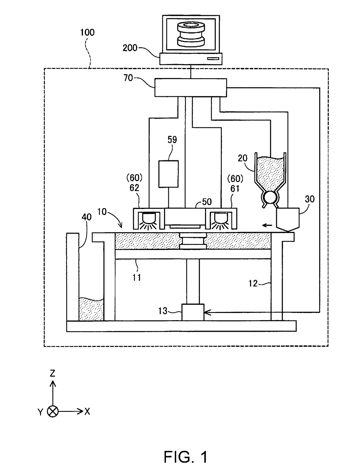
[0034]FIG. 1 is an explanatory diagram showing the schematic configuration of a three-dimensional modeling apparatus as a first embodiment of the invention. A three-dimensional modeling apparatus 100 is provided with a modeling unit 10, a powder supply unit 20, a flattening mechanism 30, a powder collecting unit 40, a head unit 50, a curing energy applying unit 60, and a control unit 70. A computer 200 is connected to the control unit 70. The three-dimensional modeling apparatus 100 and the computer 200 can be collectively regarded as a “three-dimensional modeling apparatus” in a broad sense. In FIG. 1, an X direction, a Y direction and a Z direction that intersect orthogonally to one another are shown. The Z direction is a direction along a vertical direction, and the X direction is a direction along a horizontal direction. The Y direction is a direction perpendicular to the Z direction and the X direction.

[0035]The modeling unit 10 is a tank-shaped structure in ...

second embodiment

B. Second Embodiment

[0068]FIG. 9 is an explanatory diagram showing the schematic configuration of a head unit 50A of a second embodiment. The head unit 50A of the second embodiment has a configuration the same as that of the head unit 50 of the first embodiment, except that the arrangement of the nozzle groups is different. In the head unit 50A, a fifth A nozzle group 51A for discharging droplets of cyan (C) ink, a fifth B nozzle group 52A for discharging droplets of yellow (Y) ink, a fifth C nozzle group 53A for discharging droplets of magenta (M) ink, a fifth D nozzle group 54A for discharging droplets of black (BK) ink, a sixth nozzle group 56A for discharging droplets of the first clear (CL1) ink, and a seventh nozzle group 57A for discharging droplets of the second clear (CL2) ink are aligned in this order in the main scanning direction (X direction). The nozzle groups 51A to 54A are also referred to as “fifth nozzle group GN5” collectively.

[0069]FIGS. 10A to 10F are diagrams s...

third embodiment

C. Third Embodiment

[0075]FIGS. 11A to 11F are diagrams showing an example of unit grilles in a third embodiment. In FIGS. 11A to 11C, a unit grille UG1i and a unit grille UG2j after colored ink and colorless ink were discharged are illustrated, and in FIGS. 11D to 11F, a unit grille UG1k and a unit grille UG2m are illustrated. The unit grilles UG1i to UG2m of the third embodiment are configured such that clear ink is necessarily discharged into the top portion. Note that the unit grilles UG1i to UG2m of the third embodiment do not have sub unit grilles SU. The control unit 70 causes one or more types of colored ink C, M, Y, and BK to be discharged into each of the unit grilles UG1i to UG2m, and then causes the clear ink CL, which is colorless ink, to be discharged into the unit grille UG, thereby filling the spatial volume of the unit grille UG with both the colored ink and the colorless ink, and forming a clear ink layer at the top portion of the unit grille UG.

[0076]A head unit of...


PUM

PropertyMeasurementUnit
volumeaaaaaaaaaa
volumeaaaaaaaaaa
coloraaaaaaaaaa

Abstract

A three-dimensional modeling apparatus is provided with a head unit for modeling an object by discharging a liquid into each unit grille and a control unit for controlling the head unit. The control unit controls the head unit so as to discharge a designated type of colored liquid into a first unit grille out of two unit grilles adjacent to each other in a direction from a surface of the object to the interior, and discharge, into a second unit grille, one or more types of colored liquids that includes at least one colored liquid of the same type as the colored liquid discharged into the first unit grille, so as to be able to express a color of the surface of the object using the colored liquid discharged into the first unit grille and the one or more colored liquids discharged into the second unit grille.

Description

BACKGROUND[0001]1. Technical Field[0002]The present invention relates to a three-dimensional modeling apparatus.[0003]2. Related Art[0004]In recent years, three-dimensional modeling apparatuses that adopt an inkjet technique have been attracting attention. With three-dimensional modeling apparatuses that adopt an inkjet technique, a three-dimensional object is modeled by performing, over a number of layers in the height direction (Z direction), a step of discharging a liquid having curability and forming a cross section body for one layer that lies in the horizontal direction (XY directions). For example, with a three-dimensional modeling apparatus described in JP-A-2011-73163, the color intensity is expressed by superimposing layers in which a peripheral portion is colored and layers in which a peripheral portion is not colored.[0005]JP-A-2011-73163, JP-A-2001-150556, JP-A-2005-67138 and JP-A-2010-58519 are examples of related art.[0006]However, with the technique described in JP-A...

Claims


Application Information

Patent Timeline
Patent Type & Authority Patents(United States)
IPC IPC(8): B29C67/00B29C64/112B29C64/386B33Y30/00B33Y10/00B33Y50/02
CPCB29C64/112B29C64/386B33Y10/00B33Y50/02B33Y30/00B29C64/393H04N1/60
Inventor WADA, HIROSHI
Owner SEIKO EPSON CORP
Why Eureka
Try Eureka