Wire harness cutting equipment for electronic product maintenance
A technology for electronic products and cutting equipment, applied in the field of wire harness cutting equipment for maintenance of electronic products, can solve the problems of easy cutting hands, time-consuming and labor-intensive, unsafe, etc.
- Summary
- Abstract
- Description
- Claims
- Application Information
AI Technical Summary
Problems solved by technology
Method used
Image

Examples
Embodiment 1
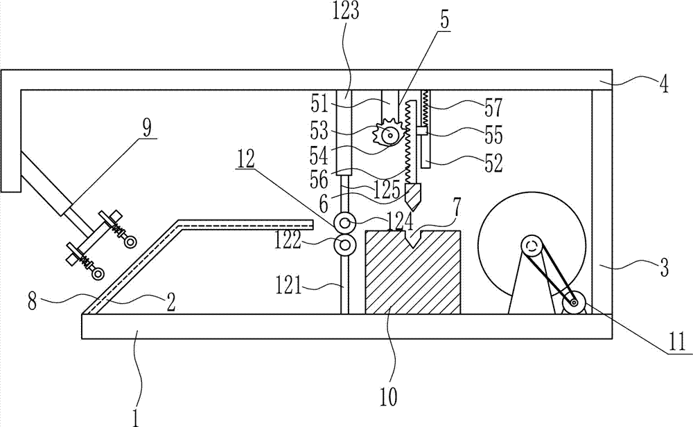
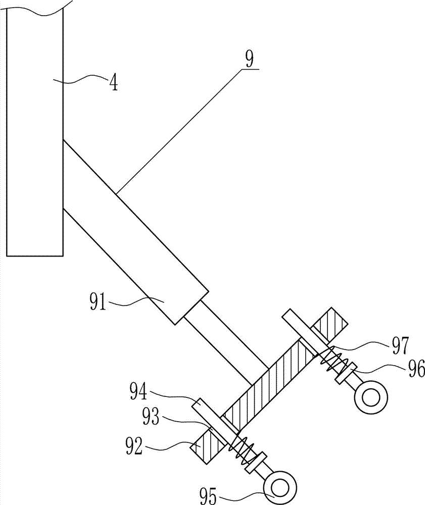
[0037] A wire harness cutting equipment for electronic product maintenance, such as Figure 1-7 As shown, it includes a bottom plate 1, a connecting plate 2, a bracket 3, an L-shaped top plate 4, a lifting mechanism 5, a cutter 6, a positioning guide device 9 and a fixing seat 10. The top of the bottom plate 1 is connected by bolts from left to right in sequence. The connecting plate 2, the fixing seat 10 and the bracket 3 are connected, and the top of the bracket 3 is connected horizontally with the L-shaped top plate 4 by means of bolts. A cutter 6 is connected, and a positioning guide device 9 is arranged on the left side of the L-shaped top plate 4. The positioning guide device 9 corresponds to the connecting plate 2. The inner top of the connecting plate 2 is provided with a groove 8, and the top of the fixed seat 10 is provided with a knife groove in the middle. 7. The knife groove 7 corresponds to the cutting knife 6 up and down, and the knife groove 7 is matched with t...
Embodiment 2
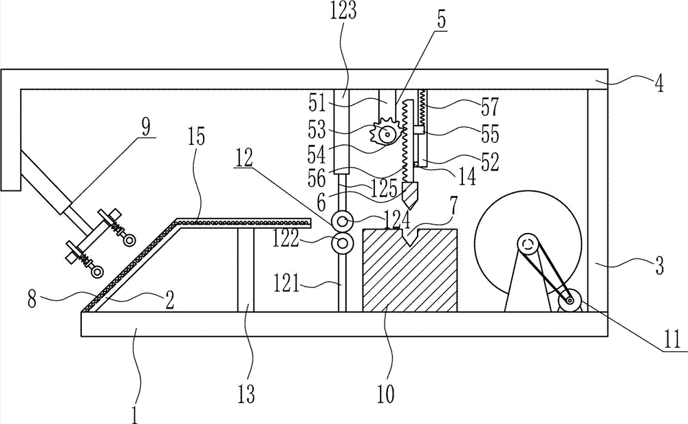
[0039] A wire harness cutting equipment for electronic product maintenance, such as Figure 1-7 As shown, it includes a bottom plate 1, a connecting plate 2, a bracket 3, an L-shaped top plate 4, a lifting mechanism 5, a cutter 6, a positioning guide device 9 and a fixing seat 10. The top of the bottom plate 1 is connected by bolts from left to right in sequence. The connecting plate 2, the fixing seat 10 and the bracket 3 are connected, and the top of the bracket 3 is connected horizontally with the L-shaped top plate 4 by means of bolts. A cutter 6 is connected, and a positioning guide device 9 is arranged on the left side of the L-shaped top plate 4. The positioning guide device 9 corresponds to the connecting plate 2. The inner top of the connecting plate 2 is provided with a groove 8, and the top of the fixed seat 10 is provided with a knife groove in the middle. 7. The knife groove 7 corresponds to the cutting knife 6 up and down, and the knife groove 7 is matched with t...
Embodiment 3
[0042] A wire harness cutting equipment for electronic product maintenance, such as Figure 1-7 As shown, it includes a bottom plate 1, a connecting plate 2, a bracket 3, an L-shaped top plate 4, a lifting mechanism 5, a cutter 6, a positioning guide device 9 and a fixing seat 10. The top of the bottom plate 1 is connected by bolts from left to right in sequence. The connecting plate 2, the fixing seat 10 and the bracket 3 are connected, and the top of the bracket 3 is connected horizontally with the L-shaped top plate 4 by means of bolts. A cutter 6 is connected, and a positioning guide device 9 is arranged on the left side of the L-shaped top plate 4. The positioning guide device 9 corresponds to the connecting plate 2. The inner top of the connecting plate 2 is provided with a groove 8, and the top of the fixed seat 10 is provided with a knife groove in the middle. 7. The knife groove 7 corresponds to the cutting knife 6 up and down, and the knife groove 7 is matched with t...
PUM
 Abstract
Description
Claims
Application Information
 - R&D
- Intellectual Property
- Life Sciences
- Materials
- Tech Scout
- Unparalleled Data Quality
- Higher Quality Content
- 60% Fewer Hallucinations
Browse by: Latest US Patents, China's latest patents, Technical Efficacy Thesaurus, Application Domain, Technology Topic, Popular Technical Reports.
© 2025 PatSnap. All rights reserved.Legal|Privacy policy|Modern Slavery Act Transparency Statement|Sitemap|About US| Contact US: help@patsnap.com