
Vehicular body structure

A body and automobile technology, applied in the sub-structure, super-structure, super-structure sub-assemblies, etc., can solve the problems such as the inability to properly configure the partition beams and reinforcements, so as to improve the leg space, improve the comfort, The effect of increasing rigidity

Active Publication Date: 2017-08-11
HONDA MOTOR CO LTD
View PDF6 Cites 4 Cited by
  • Summary
  • Abstract
  • Description
  • Claims
  • Application Information

AI Technical Summary

Problems solved by technology

In addition, there is a problem that even if the upper end of the front floor tunnel is made lower than the upper end of the upper bend in order to ensure the legroom of the occupant, the bulkhead cross member as a reinforcing member cannot be properly arranged in the structure of the above-mentioned prior art. and reinforcements

Method used


Image

  • Vehicular body structure
  • Vehicular body structure
  • Vehicular body structure

Examples


Embodiment Construction

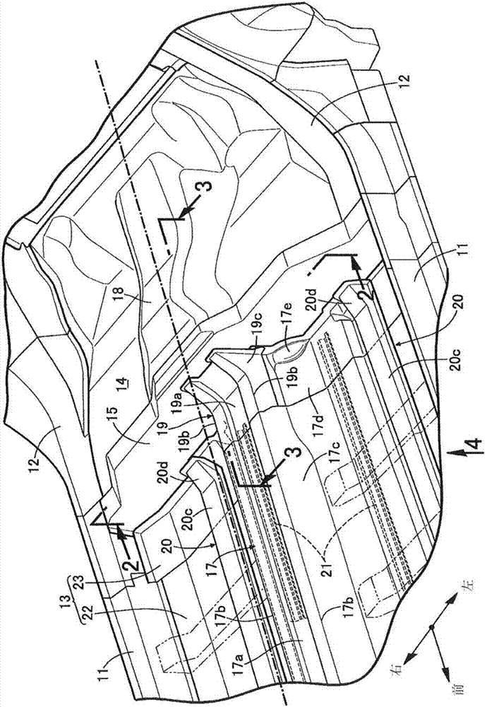
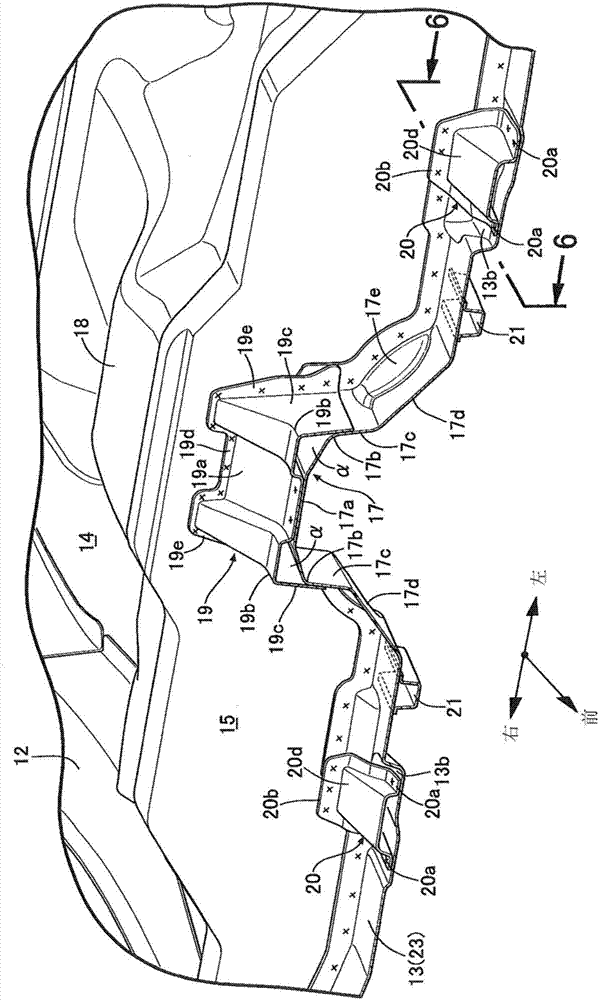
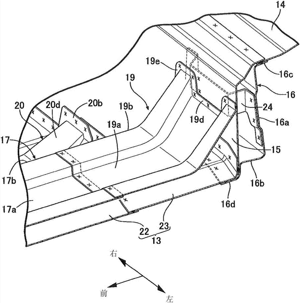
[0042] Below, according to Figure 1 to Figure 6 , the embodiment of the present invention will be described. In addition, in this specification, the front-rear direction, the left-right direction (vehicle width direction), and the up-down direction are defined based on the occupant seated in the driver's seat.

[0043] Such as figure 1 As shown, the pair of left and right side beams 11, 11 are arranged in the front-rear direction along the left and right sides of the vehicle, and the front ends of the pair of left and right rear side frames 12, 12 extending in the front-rear direction are connected to the rear of the side beams 11, 11. end. The left and right side beams 11, 11 are connected by the front floor 13 constituting the floor surface of the vehicle compartment, and the left and right rear side frames 12, 12 are connected by the floor surface constituting the lower part of the rear seat and the rear floor 14 constituting the floor surface of the cargo compartment. ...


PUM


Abstract

A tunnel reinforcing member is attached to a front floor tunnel. Second upper wall and second side walls of the tunnel reinforcing member are connected to a first upper wall and first side walls of the front floor tunnel, respectively, such that spaces are formed between second edge portions of the tunnel reinforcing member and first edge portions of the front floor tunnel. A rear portion of the first upper wall of the front floor tunnel faces a lower wall of a cross member with a kick-up part in between. A rear portion of the second upper wall of the tunnel reinforcing member inclines upwards and rearwards so as to be separated apart from the first upper wall of the front floor tunnel and faces a section reinforcing member fixed to the cross member with the kick-up part in between.

Description

technical field [0001] The present invention relates to a vehicle body structure in which a kick upsection, a bend between a front floor and a rear floor having a front floor tunnel, is reinforced with a tunnel reinforcement member. Improve body rigidity. Background technique [0002] According to the following patent document 1, a structure is known in which the rear end of the front floor tunnel provided on the front floor is connected to a cross member provided on the rear surface of the upper curved part of the front floor, and a cross member is used for the bulkhead. (bulkhead cross member: bulkhead cross member) and a pair of stiffeners located on both sides of the bulkhead cross member in the vehicle width direction reinforce the connection between the front floor tunnel and the cross member. [0003] prior art literature [0004] patent documents [0005] Patent Document 1: Japanese Invention Patent Grant Gazette Patent No. 3144502 Contents of the invention [...

Claims


Application Information

Patent Timeline
Patent Type & Authority Applications(China)
IPC IPC(8): B62D21/02B62D25/20
CPCB62D21/02B62D25/20B62D25/2027B62D25/2036B62D21/10B62D25/2009B62D27/02
Inventor 桦山昌平
Owner HONDA MOTOR CO LTD
Learn More