Vehicle frame central piece of multi-rotor unmanned aerial vehicle

A multi-rotor unmanned aerial vehicle and machine frame technology, which is applied to rotorcraft, aircraft parts, fuselage frames, etc., can solve the problems of slow production efficiency, difficult maintenance, low structural reliability, etc. Maintenance, good repeatability of product quality

Pending Publication Date: 2017-08-11
丰翼科技(深圳)有限公司
View PDF6 Cites 0 Cited by
  • Summary
  • Abstract
  • Description
  • Claims
  • Application Information

AI Technical Summary

Problems solved by technology

The structure of injection molded parts is suitable for very large batch production, and small and light-loaded drones; the production efficiency of continuous fiber-reinforced plastic integral molding structure is slow, and the product quality is difficult to repeat; the plate-rod combination structure is complex to assemble, difficult to maintain, and low in structural reliability.

Method used


Image

  • Vehicle frame central piece of multi-rotor unmanned aerial vehicle
  • Vehicle frame central piece of multi-rotor unmanned aerial vehicle
  • Vehicle frame central piece of multi-rotor unmanned aerial vehicle

Examples


Embodiment 1

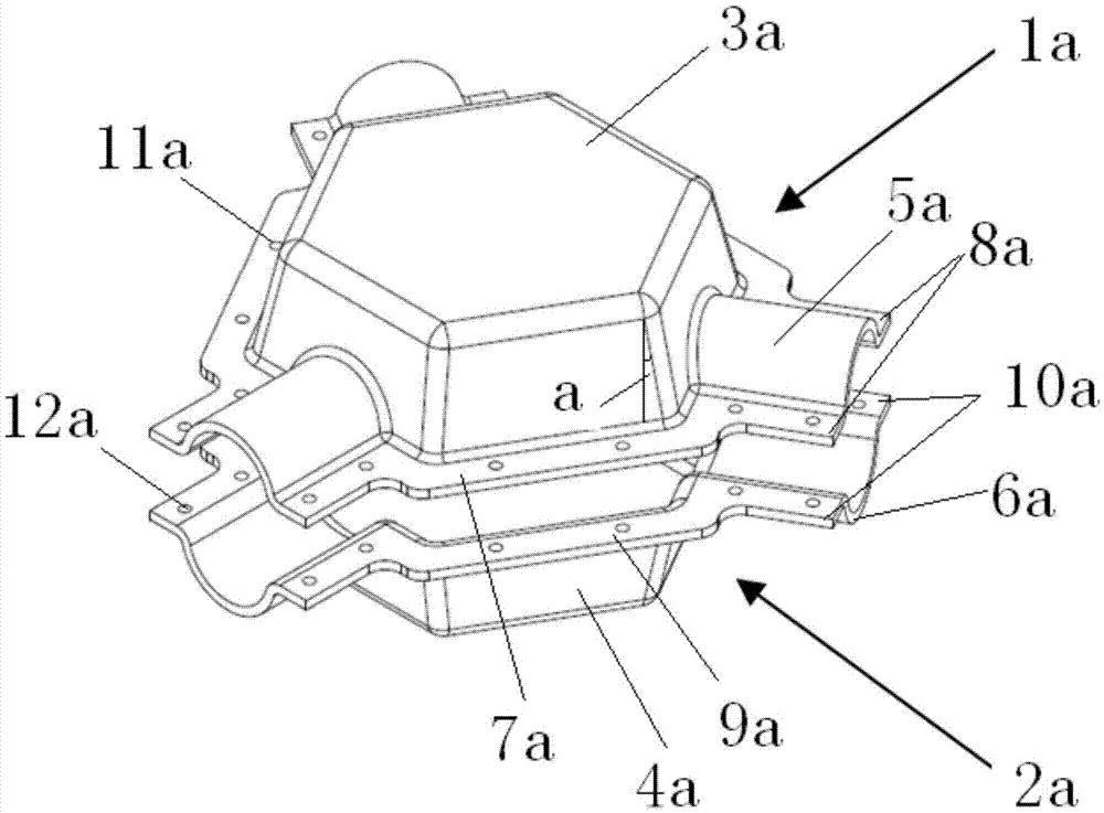
[0031] refer to figure 1 , this embodiment provides a multi-rotor UAV frame center piece, including an upper piece 1a and a lower piece 2a, and the upper piece 1a and the lower piece 2a are respectively integral structures;

[0032] The upper part 1a includes a hollow polygonal central disk upper half 3a and a plurality of pipe clamp upper halves 5a extending outward from the outer edge of the central disk upper half 3a;

[0033] The lower part 2a includes a hollow polygonal center plate lower half 4a corresponding to the center plate upper half 3a and a plurality of pipe clip upper half 5a corresponding to the outer edge of the center plate lower half 4a A plurality of pipe clamp lower halves 6a extending outward;

[0034] The upper half 3a of the central disk is connected with the lower half 4a of the central disk to form a central disk;

[0035] The pipe clamp upper half 5a is connected with the corresponding pipe clamp lower half 6a to form a pipe clamp.

[0036] The ab...

Embodiment 2

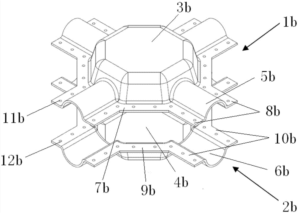
[0056] refer to figure 2 , this embodiment provides a multi-rotor UAV frame center piece, including an upper piece 1b and a lower piece 2b, and the upper piece 1b and the lower piece 2b are respectively integral structures;

[0057] The upper part 1b includes a hollow polygonal central disk upper half 3b and a plurality of pipe clip upper halves 5b extending outward from the outer edge of the central disk upper half 3b;

[0058] The lower part 2b includes a hollow polygonal center plate lower half 4b corresponding to the center plate upper half 3b and a plurality of pipe clip upper half 5b corresponding to the outer edge of the center plate lower half 4b A plurality of pipe clamp lower halves 6b extending outward;

[0059] The upper half 3b of the central disk is connected with the lower half 4b of the central disk to form a central disk;

[0060] The pipe clamp upper half 5b is connected with the corresponding pipe clamp lower half 6b to form a pipe clamp.

[0061] The ab...

Embodiment 3

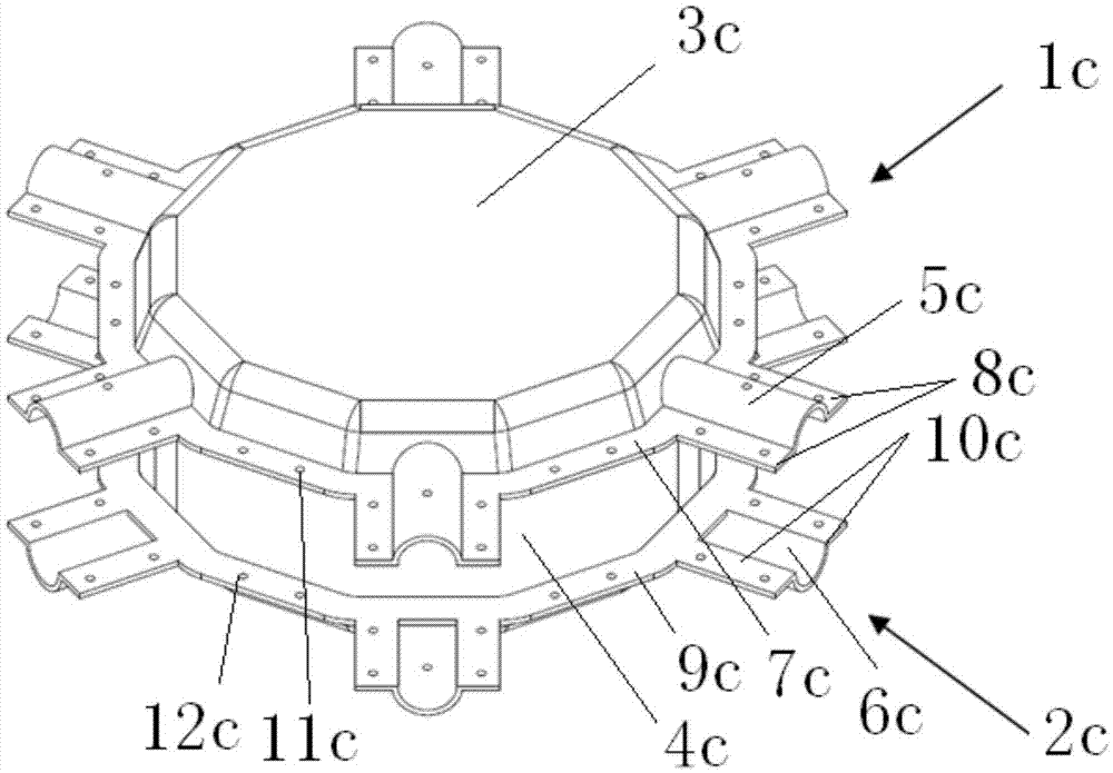
[0080] refer to image 3 , this embodiment provides a multi-rotor UAV frame center piece, including an upper piece 1c and a lower piece 2c, and the upper piece 1c and the lower piece 2c are respectively integral structures;

[0081] The upper part 1c includes a hollow polygonal central disk upper half 3c and a plurality of pipe clip upper halves 5c extending outward from the outer edge of the central disk upper half 3c;

[0082] The lower part 2c includes a hollow polygonal center plate lower half 4c corresponding to the center plate upper half 3c and a plurality of pipe clip upper half 5c corresponding to the outer edge of the center plate lower half 4c. A plurality of pipe clamp lower halves 6c extending outward;

[0083] The upper half 3c of the central disk is connected with the lower half 4c of the central disk to form a central disk;

[0084] The pipe clamp upper half 5c is connected with the corresponding pipe clamp lower half 6c to form a pipe clamp.

[0085] The ab...


PUM


Abstract

The invention provides a vehicle frame central piece of a multi-rotor unmanned aerial vehicle. The vehicle frame central piece comprises an upper piece body and a lower piece body which are each of an integrated structure. The upper piece body comprises an upper half part of a hollow polygonal central disc and a plurality of pipe clamp upper half parts outwards extending from the outer edge of the central disc upper half part. The lower piece body comprises a lower half part, corresponding to the central disc upper half part, of the hollow polygonal central disc and a plurality of pipe clamp lower half parts which are arranged corresponding to the pipe clamp upper half parts and outwards extend from the outer edges of the central disc lower half part. Disc openings of the central disc upper half part and the central disc lower half part are connected to form the central disc. The pipe clamp upper half parts and the corresponding pipe clamp lower half parts are connected to form pipe clamps. The vehicle frame central piece of the multi-rotor unmanned aerial vehicle can be manufactured from continuous fiber reinforced plastic, a mold pressing or RTM process is adopted, and product quality stability is good.

Description

technical field [0001] The invention relates to the field of unmanned aerial vehicles, in particular to a frame centerpiece of a multi-rotor unmanned aerial vehicle. Background technique [0002] A multi-rotor UAV consists of multiple cantilever-supported motors and propellers, connected by a central plate. There are several modes in the prior art: the overall structure of injection molded parts, the integral molding structure of continuous fiber reinforced plastics, or the combined structure of plates and rods. The structure of injection molded parts is suitable for very large batch production, and small and light-loaded UAVs; the production efficiency of continuous fiber-reinforced plastic integral molding structure is slow, and the product quality is difficult to repeat; the plate-rod combination structure is complex to assemble, difficult to maintain, and low in structural reliability. Contents of the invention [0003] In view of the above-mentioned defects or defici...

Claims


Application Information

Patent Timeline
Patent Type & Authority Applications(China)
IPC IPC(8): B64C1/06B64C27/08
CPCB64C1/068B64C27/08B64C2230/28
Inventor 彭兴林雷鹏涛陆再政
Owner 丰翼科技(深圳)有限公司
Why Eureka
Try Eureka