
Method for establishing the corresponding relationship between the transformer winding deformation fault and sweep frequency impedance characteristic

A technology of transformer winding and frequency sweep impedance, applied in the field of transformers, can solve the problems of low sensitivity, unintuitive test results of frequency response analysis method, and inability to locate winding faults, and achieve the effect of improving diagnosis accuracy.

Active Publication Date: 2017-08-11
STATE GRID CORP OF CHINA +1
View PDF6 Cites 21 Cited by
  • Summary
  • Abstract
  • Description
  • Claims
  • Application Information

AI Technical Summary

Problems solved by technology

However, in practical applications, both of them also have some disadvantages: the test results of the frequency response analysis method are not intuitive, and there is no quantitative judgment standard available, and experienced testers need to compare the historical data horizontally and vertically; clear, but the winding fault cannot be located, and the sensitivity is low; although the frequency response analysis method has been promoted and applied at home and abroad, and has achieved certain results, there are still some uncertainties in the process of testing the frequency response curve, which makes the test Results are still uncertain

Method used


Image

  • Method for establishing the corresponding relationship between the transformer winding deformation fault and sweep frequency impedance characteristic
  • Method for establishing the corresponding relationship between the transformer winding deformation fault and sweep frequency impedance characteristic
  • Method for establishing the corresponding relationship between the transformer winding deformation fault and sweep frequency impedance characteristic

Examples


Embodiment Construction

[0040] The following will clearly and completely describe the technical solution in the present invention with reference to the accompanying drawings in the embodiments of the present invention. Obviously, the described embodiments are only some of the embodiments of the present invention, not all of them. Based on the embodiments of the present invention, all other embodiments obtained by persons of ordinary skill in the art without creative work, any modifications, equivalent replacements, improvements, etc., shall be included in the protection scope of the present invention Inside.

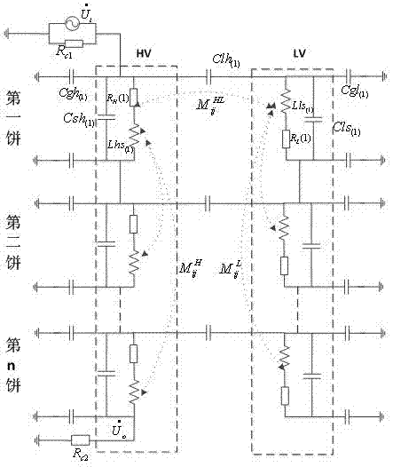
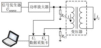
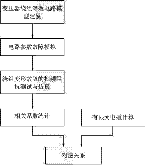
[0041] Such as figure 1 , figure 2 , image 3 , Figure 4 As shown, a method for establishing the corresponding relationship between transformer winding deformation faults and frequency-sweeping impedance features includes the following steps:

[0042] S1, such as figure 1 As shown, the equivalent circuit model of the transformer winding is established, and the equivalent circuit model is...


PUM


Abstract

The invention discloses a method for establishing the corresponding relationship between the transformer winding deformation fault and sweep frequency impedance characteristic. The method comprises the following steps: establishing an equivalent circuit model for a transformer winding; performing circuit parameter fault simulation; carrying out the sweep frequency impedance testing and simulating of a winding deformation fault; using the correlation coefficient method to calculate the relevant coefficients before and after the changes of the sweep frequency impedance curve; using the three-dimensional finite element method to calculate the electric parameters at the winding deformation state; and through the comparison and analysis of the above two, obtaining the corresponding relationship between the electric parameter change and the type of the transformer winding deformation fault. Compared with the prior art, the method of the invention can establish the corresponding relationship between the winding deformation and the sweep frequency impedance change characteristic directly and quantitatively so that deep explanation is possible for the sweep frequency impedance characteristic curve, that the transformer winding deformation diagnosing precision is increased, and that the large amount of human labor, material and financial devotion of the oil extraction hanging hood are reduced when the transformer is subject to offline maintenance.

Description

technical field [0001] The invention belongs to the technical field of transformers, in particular to a method for establishing the corresponding relationship between transformer winding deformation faults and frequency-sweeping impedance characteristics. Background technique [0002] Power transformers are important key equipment for energy conversion and transmission in power systems. However, in actual operation, transformers will inevitably be impacted by various short-circuit currents, resulting in varying degrees of deformation of the internal windings of the transformer. With the continuous increase of power system capacity, the short-circuit current level of the power grid will also increase, and the deformation of transformer windings will become more serious. [0003] The current detection methods for transformer winding deformation mainly include the following: [0004] 1. Maintenance of the hanging cover, this method is time-consuming and laborious, and the effe...

Claims


Application Information

Patent Timeline
IPC IPC(8): G01R31/06G01R31/02
CPCG01R31/62G01R31/72
Inventor 崔迎龙洁许根喜
Owner STATE GRID CORP OF CHINA
Learn More