A laminated chip power distribution module and its manufacturing method

A technology for distributing modules and power, which is applied in the electronic field, can solve the problems of large insertion loss, large space occupation, and inconvenient assembly, and achieve the effects of small insertion loss, high installation efficiency, and high reliability

Active Publication Date: 2022-04-29
SHENZHEN ZHENHUA FU ELECTRONICS +1
View PDF8 Cites 0 Cited by
  • Summary
  • Abstract
  • Description
  • Claims
  • Application Information

AI Technical Summary

Problems solved by technology

[0003] The main purpose of the present invention is to provide a laminated chip power distribution module, which aims to solve the problems of traditional power distribution modules such as large space occupation, inconvenient assembly, low isolation and large insertion loss

Method used

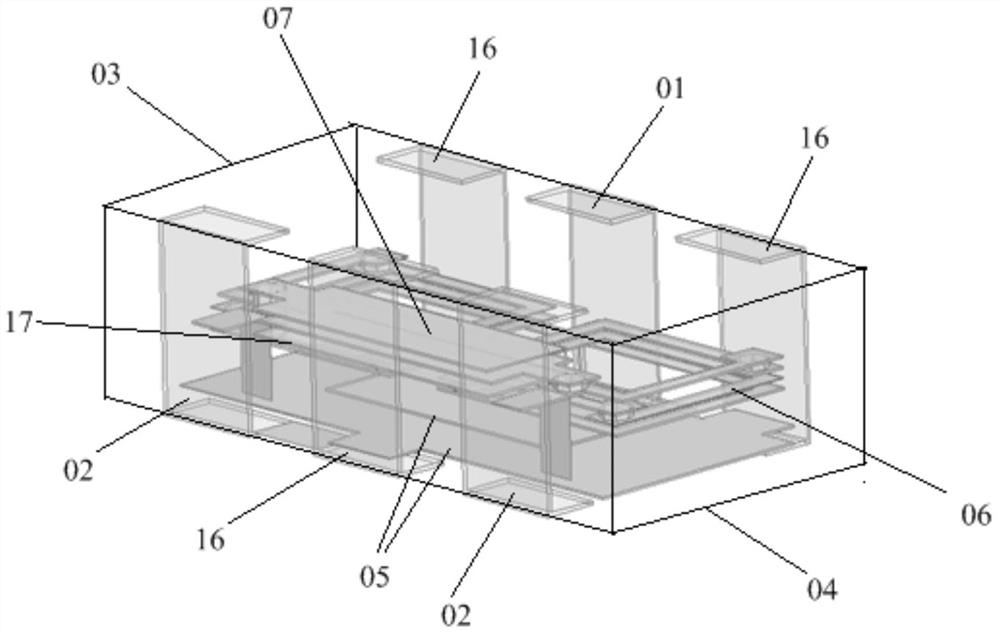
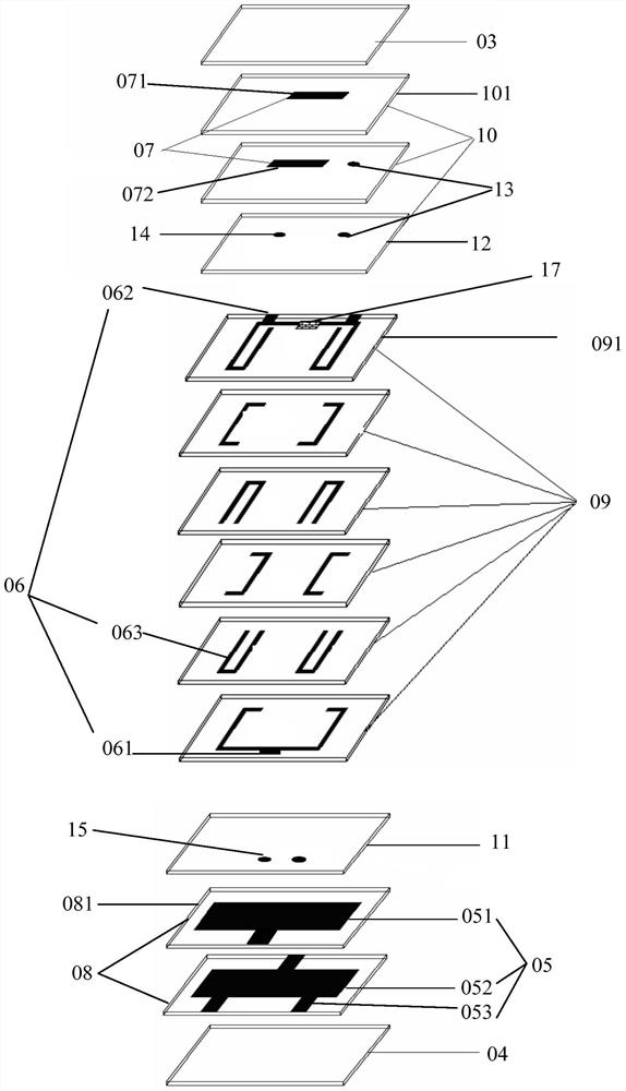
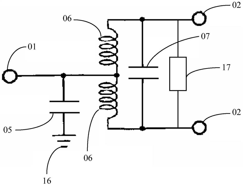

Image

  • A laminated chip power distribution module and its manufacturing method
  • A laminated chip power distribution module and its manufacturing method
  • A laminated chip power distribution module and its manufacturing method

Examples


Embodiment Construction

[0020] In order to make the object, technical solution and advantages of the present invention clearer, the present invention will be further described in detail below in conjunction with the accompanying drawings and embodiments. It should be understood that the specific embodiments described here are only used to explain the present invention, not to limit the present invention.

[0021] It should be noted that when an element is referred to as being “fixed” or “disposed on” another element, it may be directly on the other element or be indirectly on the other element. When an element is referred to as being "connected to" another element, it can be directly connected to the other element or indirectly connected to the other element.

[0022] It should also be noted that the orientation terms such as left, right, up, and down in the embodiments of the present invention are only relative concepts or refer to the normal use state of the product, and should not be regarded as r...


PUM


Abstract

The invention provides a laminated chip power distribution module, which includes an input electrode, an output electrode, an upper cover, a lower cover, and an intermediate layer, and the intermediate layer includes an inner electrode of a bypass capacitor, a power distribution coil, and an inner electrode of a coupling capacitor arranged in layers. , the number of power distribution coils is at least two and connected in parallel with each other; one end of the inner electrode of the bypass capacitor is connected to the common end of the power distribution coil, and the other end is grounded; the common end of the power distribution coil is connected to the input electrode, and the non- The common end is connected with an output electrode; an inner electrode of a coupling capacitor and an isolation resistor are connected between the non-common ends of every two parallel power distribution coils. In the present invention, the inner electrode of the bypass capacitor, the power distribution coil and the inner electrode of the coupling capacitor are laminated between the upper cover and the lower cover. High isolation, excellent phase and amplitude balance, meeting both assembly requirements and electrical performance requirements.

Description

technical field [0001] The invention belongs to the field of electronic technology, in particular to a laminated chip power distribution module and a manufacturing method thereof. Background technique [0002] With the rapid development of electronic equipment in the direction of miniaturization, light weight and integration, the volume of electronic complete machines and systems is getting smaller and smaller, and the installation density of components is also increasing. direction of development. The microwave power distribution module is a component that divides the energy of one input signal into two or more outputs with equal or unequal energy. Traditional power distribution modules are mostly assembled devices with large volume, complicated installation methods, large insertion loss, and low isolation, which cannot meet the requirements in terms of performance and assembly methods. Therefore, it is necessary to propose a new type of power distribution module to solve ...

Claims


Application Information

Patent Timeline
Patent Type & Authority Patents(China)
IPC IPC(8): H01P5/16H01P11/00
CPCH01P5/16H01P11/00
Inventor 徐鹏飞王海朱建华黄寒寒刘季超张华良王智会
Owner SHENZHEN ZHENHUA FU ELECTRONICS
Why Eureka
Try Eureka