Rainwater radial flow inverted bioretention purifier and method thereof

A purification device and bioretention technology, applied in water supply devices, chemical instruments and methods, grease/oily substance/float removal devices, etc., can solve problems such as affecting plant growth, large bioretention zone, and difficult to replace, etc. It has broad application prospects, simple mass production, and the effect of preventing soil erosion.

Active Publication Date: 2017-08-15
中规院(北京)规划设计有限公司
View PDF4 Cites 7 Cited by
  • Summary
  • Abstract
  • Description
  • Claims
  • Application Information

AI Technical Summary

Problems solved by technology

[0004] However, in the actual operation of the existing bioretention system, there are the following problems. Because the filler layer is in the lower part of the planting layer, the main primary rainwater pollutants are trapped on the surface of the planting layer, thereby causing soil pollution and affecting plant growth. At the same time, for the green belt with bare soil, it is easy to cause water and soil loss; in addition, with the increase of operation time, the pollutants in the filler layer will also increase. Since the filler layer is located below the planting layer, it is not easy to replace, thus As a result, there is a large secondary pollution problem in the traditional bioretention zone

Method used


Image

  • Rainwater radial flow inverted bioretention purifier and method thereof
  • Rainwater radial flow inverted bioretention purifier and method thereof
  • Rainwater radial flow inverted bioretention purifier and method thereof

Examples


Embodiment Construction

[0027] The specific implementation manner of the present invention will be further described in detail below in conjunction with specific examples. The following examples are only used to illustrate the present invention, and are not intended to limit the specific protection scope of the present invention.

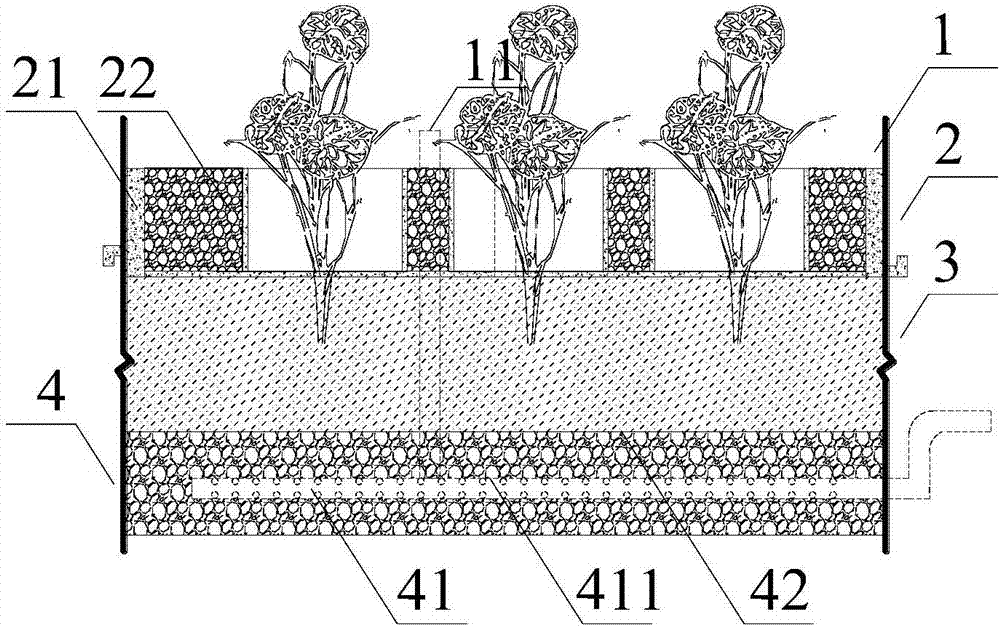
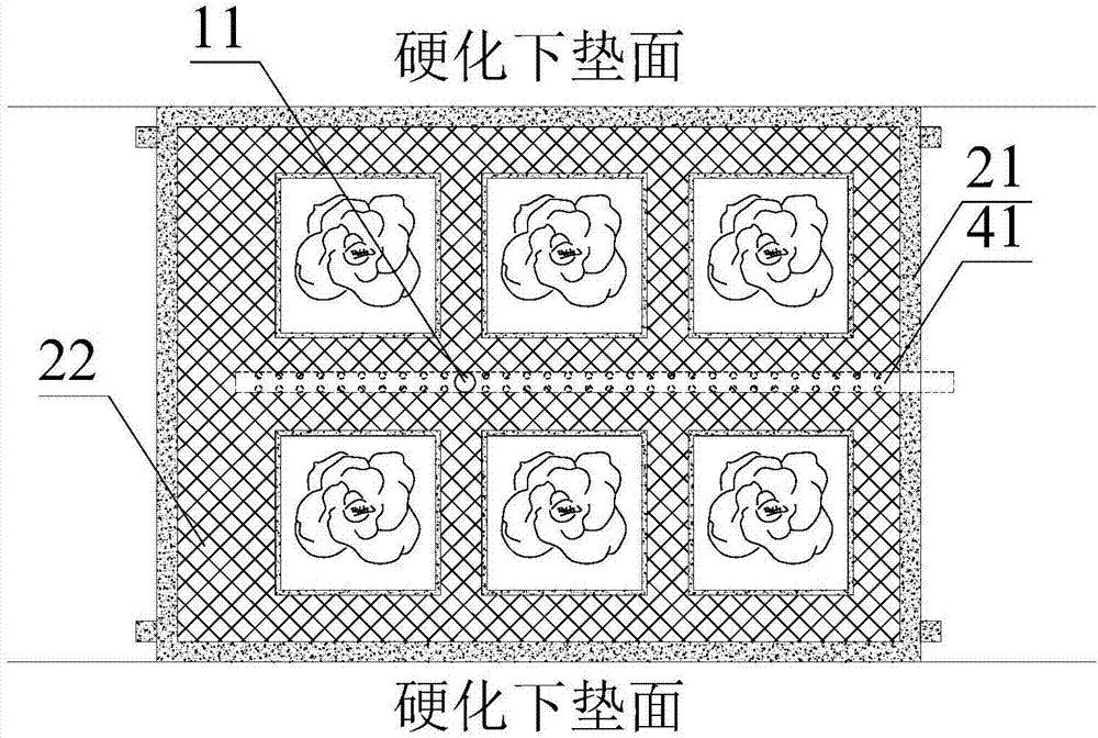
[0028] Such as figure 1 and 2 As shown, a rainwater runoff inverted bioretention purification device provided by the present invention is arranged between two adjacent hardened underlying surfaces, and sequentially includes a storage layer 1, a packing layer 2, a planting layer 3 and In the drainage layer 4, the height of the upper surface of the filler layer 2 is at least 15 cm lower than the adjacent hardened underlying surface. A perforated water collection pipe 41 is buried in the middle of the drainage layer 4. The perforated water collection pipe 41 adopts the drainage method of submerging the outflow. The perforated water collection pipe 41 The water outlet is flu...


PUM

PropertyMeasurementUnit
particle diameteraaaaaaaaaa
thicknessaaaaaaaaaa
particle diameteraaaaaaaaaa

Abstract

The invention discloses a rainwater radial flow inverted bioretention purifier and a method thereof. The rainwater radial flow inverted bioretention purifier comprises an adjustment and storage layer, a filler layer, a plantation layer and a drainage layer, the adjustment and storage layer comprises an overflow pipe which is vertically inserted and arranged in the filler layer and the plantation layer, the upper end of the overflow pipe is lower than the adjacent hardening lower padding surface by at least 5 cm, the upper end of the overflow pipe is lower than is higher than the surface of the filler layer by at least 10 cm, a perforating water collecting pipe for immersing outflow is buried at the central part of the drainage layer, the water outlet levels with the upper surface of the drainage layer, and is communicated with a city rainwater pipeline; the pollutants in the rainwater can be removed by the filler layer and the plantation layer, and the perforating water collecting pipe arranged in the adjustment and storage layer as well as the drainage layer can realize the rainwater retention. By employing the adjustment and storage layer, the filler layer, the plantation layer and the drainage layer, radial flow rainwater can be adjusted and stored, the purifier can effectively prevent water and soil loss of the plantation layer, replacing and maintenance management of the filler layer are convenient, the structural design is reasonable, production is simple, cost is low, retention purifying effect is good, and the application prospect is wide.

Description

technical field [0001] The invention relates to the technical field of rainwater runoff inversion bioretention purification, and more specifically, to a rainwater runoff inversion bioretention purification device and method. Background technique [0002] With the continuous development of the urbanization process, a large amount of pollutants are accumulated in urban rainwater runoff and directly discharged into the receiving water body, which has become one of the main factors for the deterioration of the water quality of the receiving water body. Due to the different hardened underlying surfaces, the pollution status of surface runoff is also quite different. Among them, urban roads, squares and parking lots have gradually attracted widespread attention and attention due to their relatively serious pollution. The runoff rainwater from urban roads and squares contains a large amount of petroleum aromatic organic pollutants and excessive use of deicing agents, which greatly ...

Claims


Application Information

Patent Timeline
Patent Type & Authority Applications(China)
IPC IPC(8): C02F3/32E03F3/02E03F5/00E03F5/14
CPCC02F3/32C02F2103/001E03F3/02E03F5/00E03F5/14Y02W10/10
Inventor 王建龙席广朋赵远玲赵梦圆李俊奇
Owner 中规院(北京)规划设计有限公司
Why Eureka
Try Eureka