
Light spot compression structure and light source device

A technology of light source device and light spot, which is applied in the direction of light source, lighting device, plane light source, etc., can solve the problems of difficult repair of parts, high cost of light spot compression structure, and achieve the requirements of reducing dimensional accuracy, reducing unqualified products, and reducing costs.

Active Publication Date: 2021-02-26
APPOTRONICS CORP LTD
View PDF16 Cites 0 Cited by
  • Summary
  • Abstract
  • Description
  • Claims
  • Application Information

AI Technical Summary

Problems solved by technology

The optical structure of the light spot compression structure is simple and the price is cheap. However, the light spot compression structure has extremely strict requirements on the dimensional accuracy of the mechanical components on which the reflective strips are installed. Conventional detection methods combined with optical detection methods can determine whether the mechanical components are qualified. If it is unqualified, it is difficult to repair the parts, and it is basically judged as invalid, resulting in a higher cost of the spot compression structure

Method used


Image

  • Light spot compression structure and light source device
  • Light spot compression structure and light source device
  • Light spot compression structure and light source device

Examples


Embodiment Construction

[0031] The following will clearly and completely describe the technical solutions in the embodiments of the present invention with reference to the accompanying drawings in the embodiments of the present invention. Obviously, the described embodiments are only some, not all, embodiments of the present invention. Based on the embodiments of the present invention, all other embodiments obtained by persons of ordinary skill in the art without making creative efforts belong to the protection scope of the present invention.

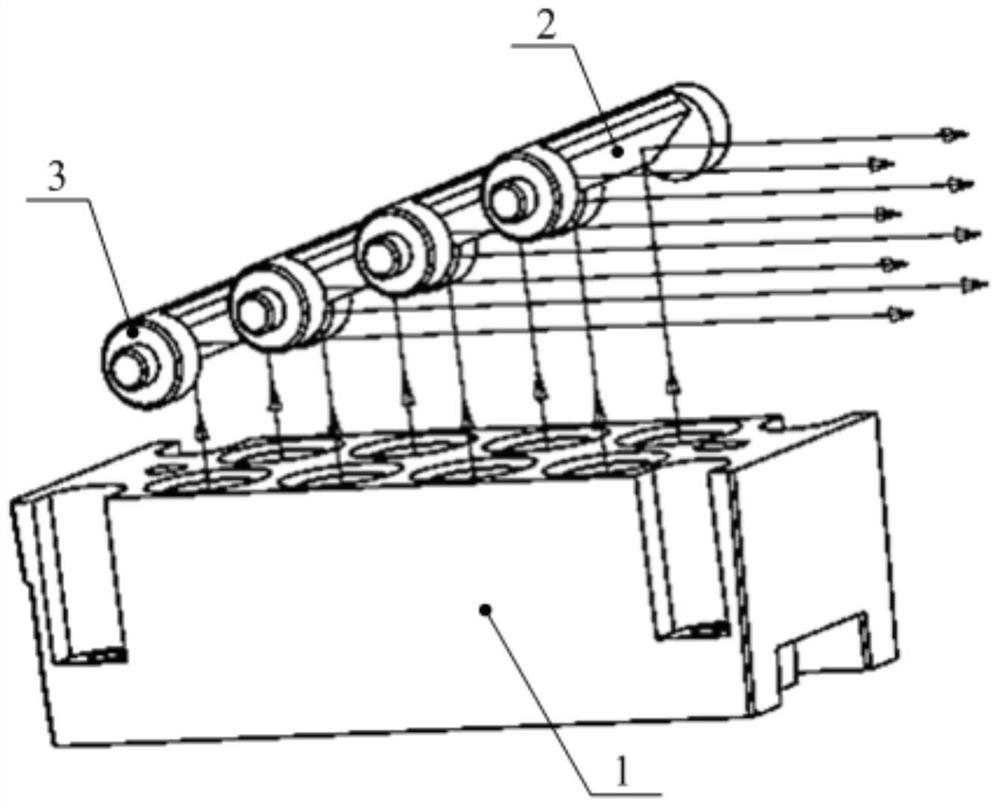
[0032] In order to reduce the cost of light spot compression, the present invention provides a light spot compression structure, which is specifically described by the following two embodiments.

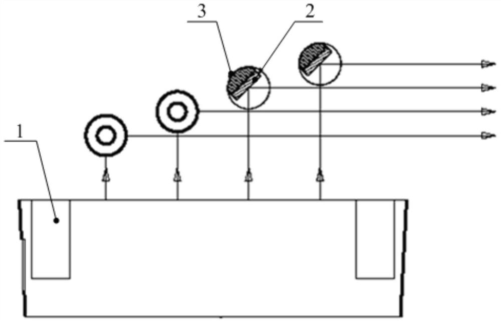
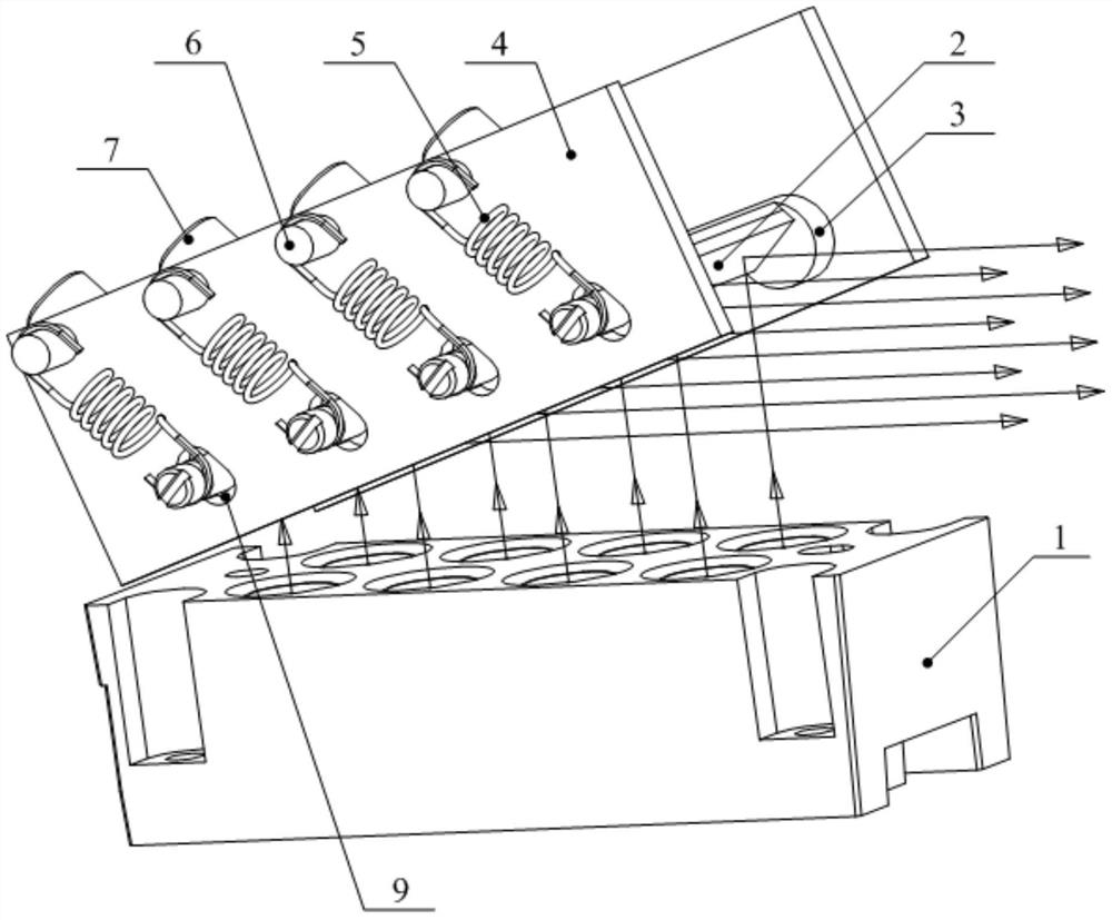
[0033] like figure 1 and figure 2 As shown, the light spot compression structure provided by Embodiment 1 of the present invention includes: a reflective strip 2 and an adjustment mechanism.

[0034] The adjustment mechanism above carries the reflective strip 2 an...


PUM


Abstract

The invention discloses a light spot compression structure and a light source device. The light spot compression structure includes: a reflection strip used to face at least two light sources; an adjustment mechanism that carries the reflection strip and can adjust the reflection angle of the reflection strip; wherein, the adjustment The mechanism includes: a bracket and an adjustment component arranged on the bracket; the reflection strip is carried on the adjustment component, and the adjustment component corresponds to the reflection strip one by one. The light spot compression structure disclosed in the present invention can adjust the reflection angle of each reflective strip by setting the adjustment mechanism, and use the adjustment mechanism to adjust the reflection angle of the reflective strips, and the adjustment components correspond to the reflective strips one by one. During the installation process of the light spot compression structure, the reflection angle of each reflective strip is adjusted, thereby reducing the requirements on the dimensional accuracy of mechanical components, improving the pass rate, reducing unqualified products, and reducing the cost of light spot compression.

Description

technical field [0001] The invention relates to the technical field of light source adjustment, and more specifically, to a light spot compression structure and a light source device. Background technique [0002] The parallel spot of the array is usually compressed by a spot compression structure to obtain the spot with the desired pitch. [0003] At present, the light spot compression structure is mainly reflective strips arranged in steps. Specifically, the light spot compression structure includes a bracket, and the reflective strips are arranged in a stepped shape on the bracket. The optical structure of the light spot compression structure is simple and cheap. However, the light spot compression structure has extremely strict requirements on the dimensional accuracy of the mechanical components on which the reflective strips are installed. Conventional detection methods combined with optical detection methods can determine whether the mechanical components are qualifie...

Claims


Application Information

Patent Timeline
Patent Type & Authority Patents(China)
IPC IPC(8): F21V14/04F21K9/20F21Y105/16F21Y115/30
CPCF21V14/04
Inventor 杨义红王则钦李屹
Owner APPOTRONICS CORP LTD
Learn More