optical module
An optical module and temperature control module technology, applied in the field of optical modules, can solve the problems of lengthening and hindering the miniaturization of optical modules, and achieve the effects of shortening the length, realizing miniaturization, and suppressing tracking errors.
- Summary
- Abstract
- Description
- Claims
- Application Information
AI Technical Summary
Problems solved by technology
Method used
Image
Examples
Embodiment approach 1
[0036] (structure)
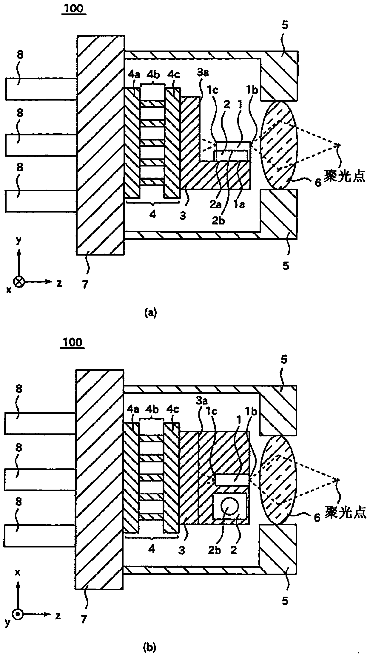
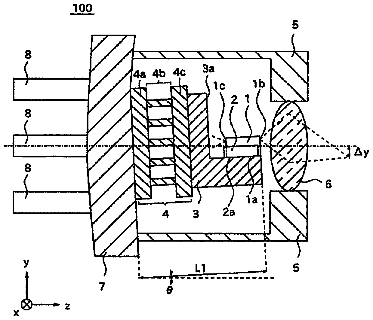
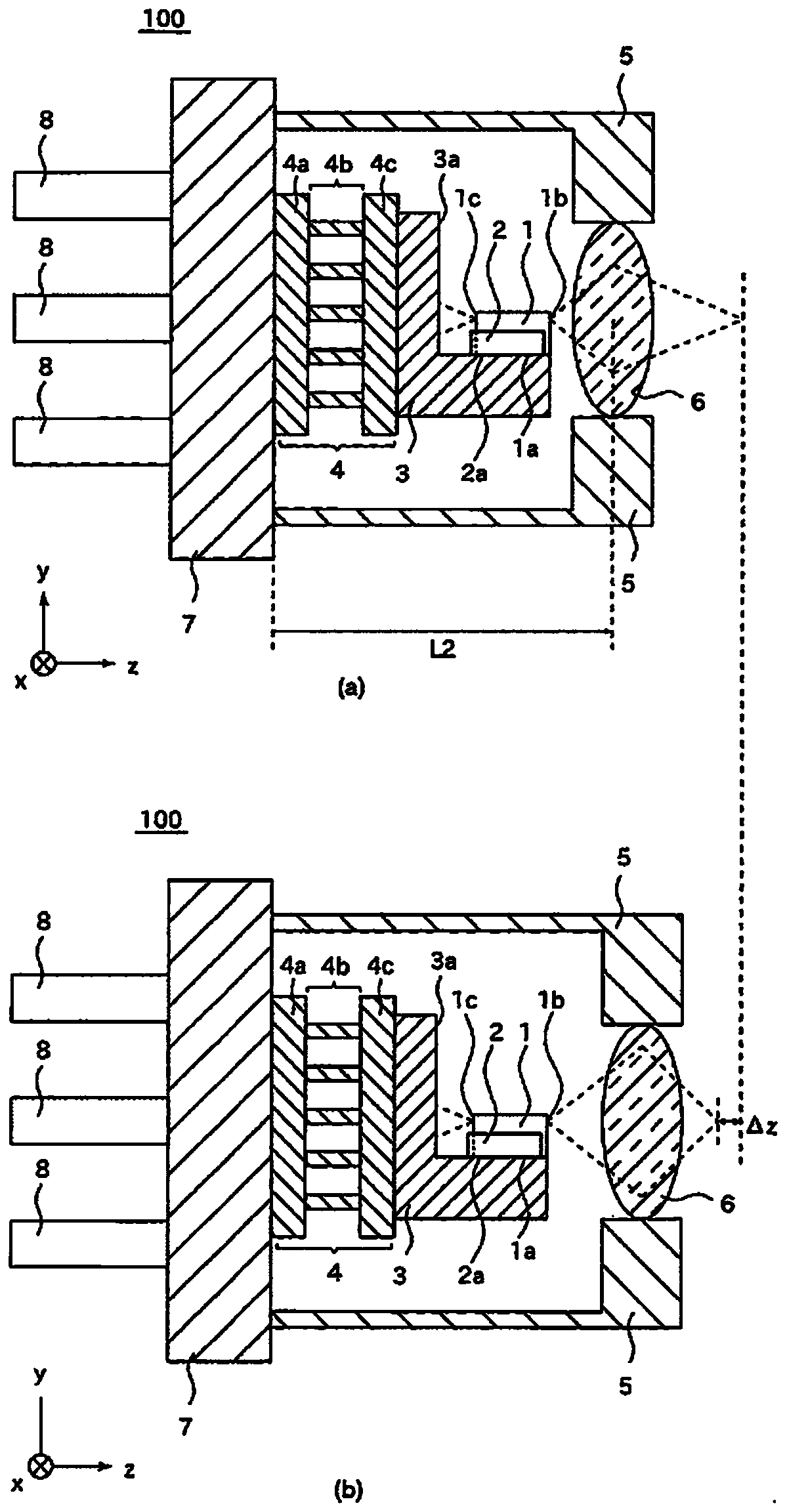
[0037] exist figure 1 A cross-sectional view of the optical module 100 according to Embodiment 1 is shown in FIG. figure 1 (a) is a cross-sectional view of the optical module 100 viewed from the x-axis direction, figure 1 (b) is a cross-sectional view viewed from the y-axis direction. The temperature control module 4 is fixed to the socket 7 . The temperature control module 4 includes a first substrate 4a, a Peltier element 4b, and a second substrate 4c. The support 3 is fixed to the temperature control module 4 . The support 3 is provided with a reflection surface 3a that reflects light. The light emitting element 1 is fixed to the support 3 via the light emitting element fixing surface 1 a. The light-emitting element 1 has a front surface 1b and a rear surface 1c. In addition, the light receiving element 2 is fixed to the support 3 via the light receiving element fixing surface 2a. The light receiving element 2 has a light receiving surface 2b. ...
Embodiment approach 2
[0063] An optical module according to Embodiment 2 of the present invention will be described. Here, the description will focus on the differences from the optical module of the first embodiment.
[0064] (structure)
[0065] Figure 7 It is a cross-sectional view of the optical module 200 according to the second embodiment. Figure 7 (a) is a cross-sectional view of the optical module 200 viewed from the x-axis direction, Figure 7 (b) is a cross-sectional view viewed from the y-axis direction. Figure 8 It is a perspective view of the support 203 of the optical module 200 of Embodiment 2. FIG. In the optical module 200 according to Embodiment 2, the support 203 is provided with the recessed portion 203b, and the light-receiving element 2 is fixed to the recessed portion 203b by the light-receiving element fixing surface 2a.
[0066] (effect of invention)
[0067] In the optical module 200 of the second embodiment, the light receiving element 2 is fixed to the recessed ...
Embodiment approach 3
[0070] An optical module according to Embodiment 3 of the present invention will be described. Here, the description will focus on the differences from the optical module of the first embodiment.
[0071] (structure)
[0072] Figure 9 It is a cross-sectional view of the optical module 300 according to the third embodiment. Figure 9 (a) is a cross-sectional view of the optical module 300 viewed from the x-axis direction, Figure 9 (b) is a cross-sectional view viewed from the y-axis direction. In the optical module 300 of the third embodiment, the light-receiving surface 302 b of the light-receiving element 302 faces the reflecting surface 3 a provided on the support 3 .
[0073] (effect of invention)
[0074] In the optical module 300 of the third embodiment, the light-receiving surface 302b of the light-receiving element 302 faces the reflecting surface 3a. Therefore, compared with the optical module 100 of the first embodiment, the light receiving element 302 receive...
PUM
 Abstract
Description
Claims
Application Information
 - R&D
- Intellectual Property
- Life Sciences
- Materials
- Tech Scout
- Unparalleled Data Quality
- Higher Quality Content
- 60% Fewer Hallucinations
Browse by: Latest US Patents, China's latest patents, Technical Efficacy Thesaurus, Application Domain, Technology Topic, Popular Technical Reports.
© 2025 PatSnap. All rights reserved.Legal|Privacy policy|Modern Slavery Act Transparency Statement|Sitemap|About US| Contact US: help@patsnap.com


