Pin bending machine

A bending machine and pin technology, applied in the field of electronic component processing equipment, can solve the problems of easy accidental damage and low efficiency of equipment, and achieve the effect of improving efficiency and realizing the processing process

Inactive Publication Date: 2017-08-18
LEIYANG YAXIANG ELECTRONICS TECH
View PDF8 Cites 31 Cited by
  • Summary
  • Abstract
  • Description
  • Claims
  • Application Information

AI Technical Summary

Problems solved by technology

[0004] Chinese patent (201520549137.2) discloses a semi-automatic bending equipment, which realizes mechanical bending and cutting of electronic component pins by installing special bending and cutting fixtures on the working table and lower pressing arm of the stamping equipment, However, in the process of processing, the pick-and-place...

Method used


Image

  • Pin bending machine
  • Pin bending machine
  • Pin bending machine

Examples


Embodiment Construction

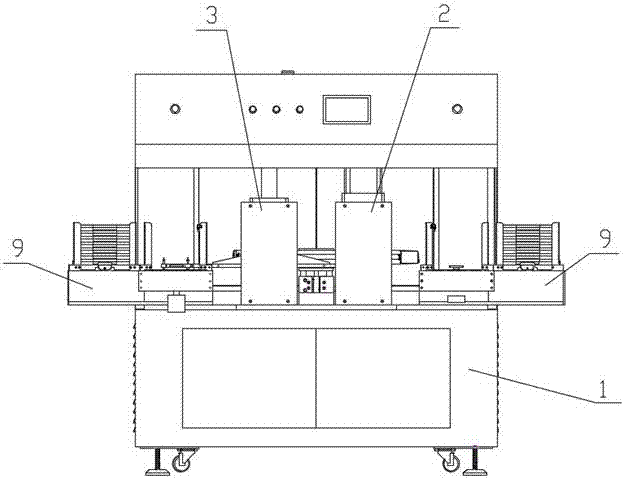
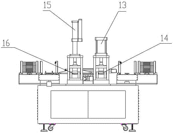
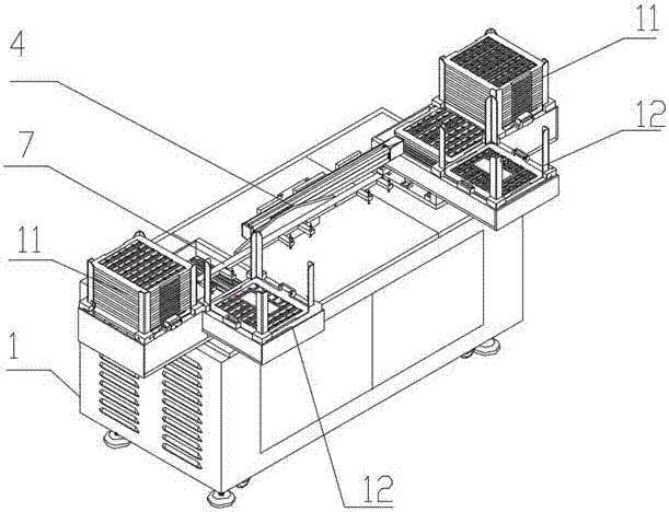
[0032] In the description of the present invention, it should be understood that the orientation or positional relationship indicated by the terms "inner", "outer" and the like are based on the orientation or positional relationship shown in the drawings, and are only for the convenience of describing the present invention and simplifying the description. It is not intended to indicate or imply that the referred device or element must have a particular orientation, be constructed in a particular orientation, and operate in a particular orientation, and thus should not be construed as limiting the invention.

[0033] In addition, the terms "mounted", "connected" and "connected" should be interpreted in a broad sense, for example, it may be a mechanical connection or an electrical connection, or an internal communication between two components, either directly or indirectly through an intermediary. In connection, those skilled in the art can understand the specific meanings of th...


PUM


Abstract

The invention relates to the technical field of electronic element machining equipment, in particular to a pin bending machine. The pin bending machine comprises a frame, and a bending device, a pin cutting device, a carrying device and a controller arranged on the frame. The pin bending machine is characterized in that the bending device and the pin cutting device are arranged in the frame side by side; the carrying device comprises a lifting cylinder vertically arranged in the frame, and a first linear slide rail horizontally mounted on a slide block of the lifting cylinder; a carrying arm is fixedly mounted on the first linear slide rail; four sucking nozzles are arranged on the carrying at equal intervals; the sucking nozzles are connected with a vacuum pump through pipelines; the gaps of an automatic feeding device, the bending device, the pin cutting device and an automatic collecting device are just equal to the gaps of the sucking nozzles; working planes for placing network transformers in the automatic feeding device, the bending device, the pin cutting device and the automatic collecting device are the same in heights; and the carrying device can synchronously finish the work of taking from a taking point to the bending device, carrying of the network transformers from the bending device to the pin cutting device and carrying from the pin cutting device to a collecting point under the control of the controller.

Description

technical field [0001] The invention relates to the technical field of electronic component processing equipment, in particular to a pin bending machine. Background technique [0002] Such as figure 1 As shown, the housing with electronic components is usually made by continuous injection molding process (that is, the housings of multiple electronic components are injection molded on a pin substrate), and after the injection molding is completed, multiple housing blanks are regularly arranged on the On the pin substrate, it is then sent to the bending process for the bending of the pins. [0003] The lead bending process actually includes two steps: 1. Bending the connected leads at a specific angle as a whole. 2. Cut off the end of the pin that is bent at a certain angle. [0004] Chinese patent (201520549137.2) discloses a semi-automatic bending equipment, which realizes mechanical bending and cutting of electronic component pins by installing special bending and cuttin...

Claims


Application Information

Patent Timeline
IPC IPC(8): B21F1/00B21F11/00B21F23/00
CPCB21F1/004B21F11/00B21F23/00
Inventor 陈小勇龚亮杨艳军朱千林
Owner LEIYANG YAXIANG ELECTRONICS TECH
Why Eureka
Try Eureka