Three-wheeled differential steering mechanism and vehicle

A differential steering and three-wheel technology, applied to steering mechanisms, non-deflectable wheel steering, vehicle components, etc., can solve the problems of limited steering angle, low resource utilization, and low space utilization, achieving small turning radius, The effect of low product cost and improved utilization

Active Publication Date: 2017-08-18
BLUECARD TECH CORP
View PDF6 Cites 0 Cited by
  • Summary
  • Abstract
  • Description
  • Claims
  • Application Information

AI Technical Summary

Problems solved by technology

[0003] The purpose of the present invention is to provide a three-wheel differential steering mechanism to solve the technical problems of high cost, low resource utilization, large turning radius, limited steering angle and low space utilization in the prior art

Method used


Image

  • Three-wheeled differential steering mechanism and vehicle
  • Three-wheeled differential steering mechanism and vehicle
  • Three-wheeled differential steering mechanism and vehicle

Examples


Embodiment 1

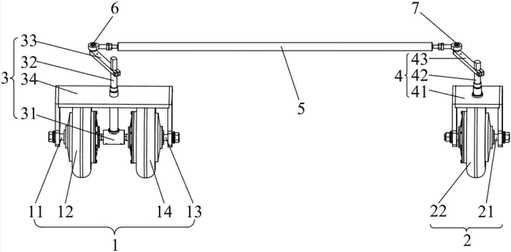
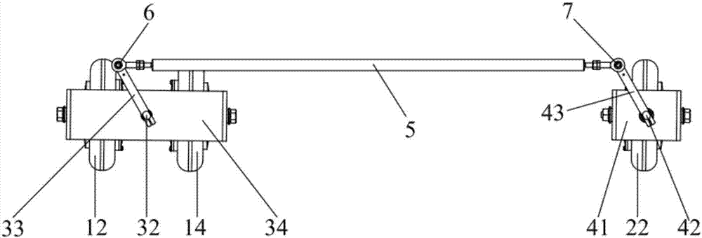
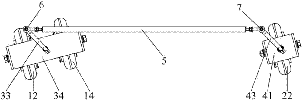
[0043] See Figure 1 to Figure 3 , A three-wheel differential steering mechanism, including a steering drive wheel set 1, a steering driven wheel set 2 and a steering transmission mechanism.

[0044] The steering drive wheel set 1 includes a first traveling wheel 12 rotatably arranged on a first axle 11 and a second traveling wheel 14 rotatably arranged on a second axle 13. The first axle 11 and the second axle 13 are fixedly connected to each other. The axle 11 and the second axle 13 themselves do not rotate. In this embodiment, the central axis of the first axle 11 and the central axis of the second axle 13 are located on the same straight line.

[0045] The steering driven wheel set 2 includes a third traveling wheel 22 rotatably arranged on the third axle 21; the steering transmission mechanism connects the steering drive wheel set 1 and the steering driven wheel set 2, and the rotational speeds of the first traveling wheel 12 and the second traveling wheel 14 The difference ...

Embodiment 2

[0057] A vehicle includes the aforementioned three-wheel differential steering mechanism, which is used to drive the vehicle forward and turn. When the three-wheel differential steering mechanism is connected to the vehicle, the shaft of the first connecting shaft 32 is rotatably connected with the wheel of the vehicle, and the shaft of the second connecting shaft 42 is rotatably connected with the wheel of the vehicle. After the installation is completed, the first The distance between the central axis of the connecting shaft 32 and the central axis of the second connecting shaft 42 is a fixed value. In this embodiment, the shaft body of the first connecting shaft 32 is rotatably connected with the wheel of the vehicle, and the shaft body of the second connecting shaft 42 is rotatably connected with the wheel of the vehicle.

[0058] The three-wheel differential steering mechanism is installed at the front end of the vehicle, and two universal wheels are installed at the rear en...


PUM


Abstract

The present invention discloses a three-wheeled differential steering mechanism and a vehicle. The three-wheeled differential steering mechanism includes a steering driving wheel set, a steering driven wheel set and a steering transmission mechanism. The steering driving wheel set includes a first running wheel rotationally arranged on a first axle, and a second running wheel rotationally arranged on a second axle, and the first axle and the second axle are fixedly connected; the steering driven wheel set includes a third running wheel rotationally arranged on a third axle; the steering transmission mechanism is used for connecting the steering driving wheel set with the steering driven wheel set, the speed difference between the first running wheel and the second running wheel can drive the steering transmission mechanism to move, and the steering transmission mechanism is used for transmitting the steering movement of the steering driving wheel set to the steering driven wheel set. The vehicle disclosed by the present invention employs the three-wheeled differential steering mechanism, and has the advantage that the turning radius is small, the vehicle can make a turn and walk in all directions and steer in a narrow space, the resource utilization ratio is high, and the product cost is low.

Description

Technical field [0001] The present invention relates to the technical field of steering control, in particular to a three-wheel differential steering mechanism and a vehicle using the three-wheel differential steering mechanism. Background technique [0002] The vehicle steering mechanism is used to control the driving direction of various wheeled or tracked vehicles. The traditional steering control mechanism is designed to satisfy the turning of the machine, and generally requires a special drive to control its turning, manpower or other power, such as bicycle and automobile steering mechanism. Simply increase the drive for steering. Normally, the drive is in an idle state, resulting in increased product costs and low resource utilization. In addition, the ordinary two-wheel differential control steering mechanism realizes steering by controlling the different rotation speeds of the two wheels. The turning radius is large and the steering angle is limited. It is difficult to a...

Claims


Application Information

Patent Timeline
Patent Type & Authority Applications(China)
IPC IPC(8): B62D11/02
CPCB62D11/006B62D11/02
Inventor 庄明华尹久春武涛李超旗宁腾飞
Owner BLUECARD TECH CORP
Why Eureka
Try Eureka