
U-type steel bracket capable of actively stabilizing surrounding rock

A technology of profiled steel and surrounding rock, which is applied in wellbore lining, tunnel lining, underground chamber, etc., can solve problems such as insufficient support performance, reduced self-supporting capacity of surrounding rock, unstable supporting structure, etc. The effect of surrounding rock stability control, surrounding rock stability, and improving support performance

Inactive Publication Date: 2017-08-18
ANHUI UNIV OF SCI & TECH
View PDF9 Cites 7 Cited by
  • Summary
  • Abstract
  • Description
  • Claims
  • Application Information

AI Technical Summary

Problems solved by technology

The traditional U-shaped steel metal support is a passive support form during the support process. The deformation of the surrounding rock in the roadway has a great influence on the U-shaped steel support, resulting in unstable support structure and difficult to obtain ideal support effects; U-shaped steel support and surrounding There are gaps between the rocks, which cannot be fully densely contacted, and are easily subjected to point loads or local excessive force, resulting in easy deformation and damage of the support, and cannot give full play to its supporting performance; it is often necessary to fill between the support and the surrounding rock in field use. Otherwise, it is easy to reduce the initial supporting force of the support to the surrounding rock, resulting in a decrease in the self-supporting capacity of the surrounding rock, resulting in excessive convergence deformation of the roadway

Method used


Image

  • U-type steel bracket capable of actively stabilizing surrounding rock
  • U-type steel bracket capable of actively stabilizing surrounding rock
  • U-type steel bracket capable of actively stabilizing surrounding rock

Examples


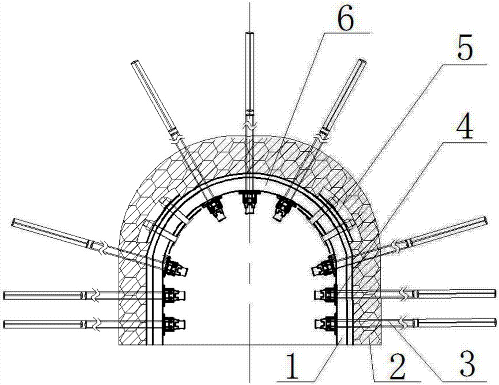
Embodiment Construction

[0027] The present invention will be further described below in conjunction with accompanying drawing:

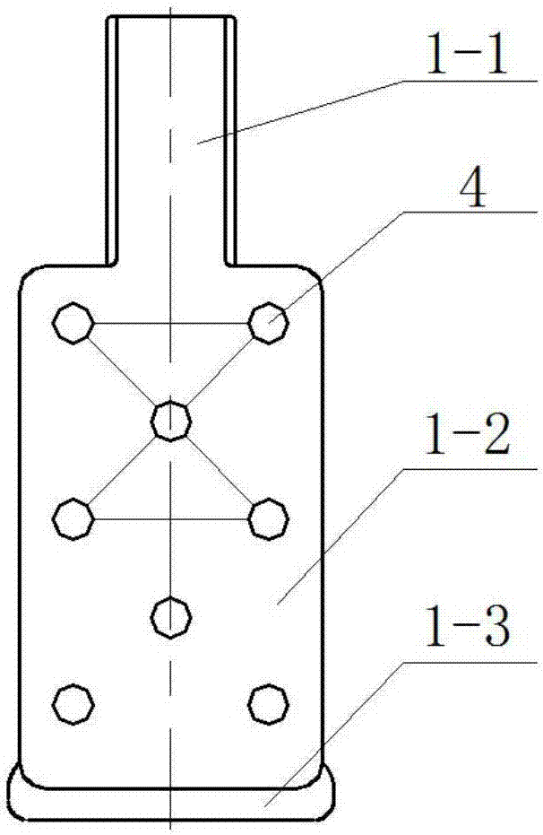
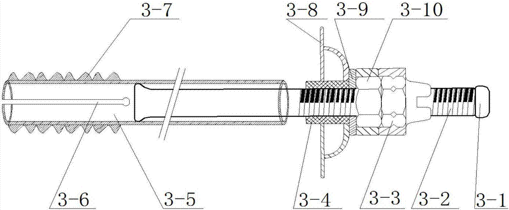
[0028]Working principle: The two ends of U-shaped steel 6 on the vault are inserted or overlapped on the bending section 1-1 of the special-shaped U-shaped steel 1 on the legs of the two sheds, and the overlapping parts of the two are fixed with clamps 5 to form a U-shaped steel bracket The basic structure; the U-shaped elastic filling element 2 is in close contact with the groove side of the arch U-shaped steel 6, and the widened edge of the special-shaped U-shaped steel 1 of the shed legs and the groove side. During the support process, it can Ensure that the filling between the bracket and the surrounding rock is dense, effectively simplify the post-filling process of the U-shaped steel wall, and the joints between adjacent U-shaped elastic filling elements 2 are processed with concave-convex meshing structures 2-1, 2-2, and the two are meshed and embedded The connection...


PUM


Abstract

The invention discloses a U-type steel bracket capable of actively stabilizing surrounding rock. The U-type steel bracket comprises arch crown U-type steel, shed leg portion special-shaped U-type steel, clamps, a U-type elastic filling element and an anchor rod expansion component, and is characterized in that the two ends of the arch crown U-type steel are inserted into or in butt joint with the bent parts of the shed leg portion special-shaped U-type steel on two sides and are connected with and fixed to the bent parts of the shed leg portion special-shaped U-type steel on two sides through the clamps; after being installed on the wall of the U-type steel bracket, the U-type elastic filling element makes tight contact with the U-type steel bracket and the surrounding rock and isolates the U-type steel bracket from the surrounding rock; the shed leg portion special-shaped U-type steel on two sides is subjected to widening treatment; and anchor rod holes are reserved in the shed leg portion special-shaped U-type steel, the arch crown U-type steel and the U-type elastic filling element, and the anchor rod expansion component penetrates through the anchor rod holes to be drilled into the surrounding rock, and forms a uniform support structure with the U-type steel bracket. The U-type steel bracket can actively apply setting load on the surrounding rock, improve the self-bearing capacity of the surrounding rock, improve the stress state of the U-type steel bracket, enhance the local and overall support strength, ensure contractibility and improve the supporting efficiency.

Description

technical field [0001] The invention relates to the technical field of coal mine underground or tunnel support, in particular to a U-shaped steel bracket capable of actively stabilizing surrounding rock. Stablize. Background technique [0002] At present, metal support technology has been widely used in tunnel support of mine roadways, railways and various underground projects at home and abroad. With the maturation of roadway metal support technology, the application in mine roadway or tunnel support is becoming more and more important. There are many types of traditional U-shaped steel brackets. Through the application of different types of U-shaped steels in engineering, it is found that the existing U-shaped steels have poor stability and uneven force during the support process, and are easy to fall under the action of point load or local load. As a passive support method, it is difficult to apply a large initial support force to the surrounding rock, and the main disa...

Claims


Application Information

Patent Timeline
IPC IPC(8): E21D11/00E21D11/18E21D20/00E21D21/00
CPCE21D11/006E21D11/18E21D11/183E21D20/00E21D21/0026E21D21/008
Inventor 张若飞刘增辉张宇博戴晨宋泽方胡佳佳
Owner ANHUI UNIV OF SCI & TECH
Learn More