Supercharge Your Innovation With Domain-Expert AI Agents!

Carriage locking pin zoom system

A lock pin and scaling technology, applied in the direction of mechanical equipment, connecting components, etc., can solve the problems of inconvenient disassembly of shelves, unsafe driving, insufficient extension force of locking pins, etc., to improve driving safety, large extension force, and easy disassembly Effect

Active Publication Date: 2017-08-18
GUANGDONG FUWA HEAVY IND
View PDF5 Cites 2 Cited by
  • Summary
  • Abstract
  • Description
  • Claims
  • Application Information

AI Technical Summary

Problems solved by technology

[0004] like figure 2 and image 3 As shown, the existing lock pin structure usually uses two opposing springs to make the locking pin extend and contract, including the push-out spring 1B and the retracting spring 2B. Since the two springs are opposed, the elastic forces cancel each other out, resulting in the extension of the locking pin. Insufficient output force, if the shelf cannot be locked, it will cause unsafe driving. Correspondingly, when shrinking the locking pin, it is necessary to provide more force to shrink the locking pin. It is necessary to increase the locking force by adding auxiliary spring 3B; When the locking pin shrinks, because each locking pin can only shrink at the same time, if one or two locking pins are stuck, the rest of the locking pins cannot shrink, and when the relative position of the shelf and the locking pin is adjusted, it will be stuck. After the locking pin removes the obstacle, the other locking pin may be stuck due to the change of the relative position with the shelf, which makes it inconvenient to disassemble the shelf.

Method used


Image

  • Carriage locking pin zoom system
  • Carriage locking pin zoom system
  • Carriage locking pin zoom system

Examples


Embodiment Construction

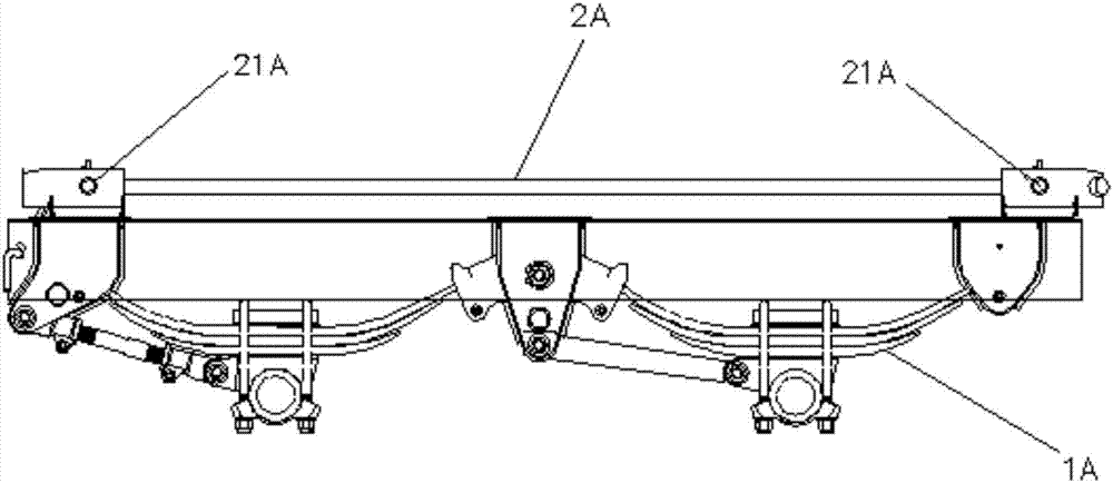
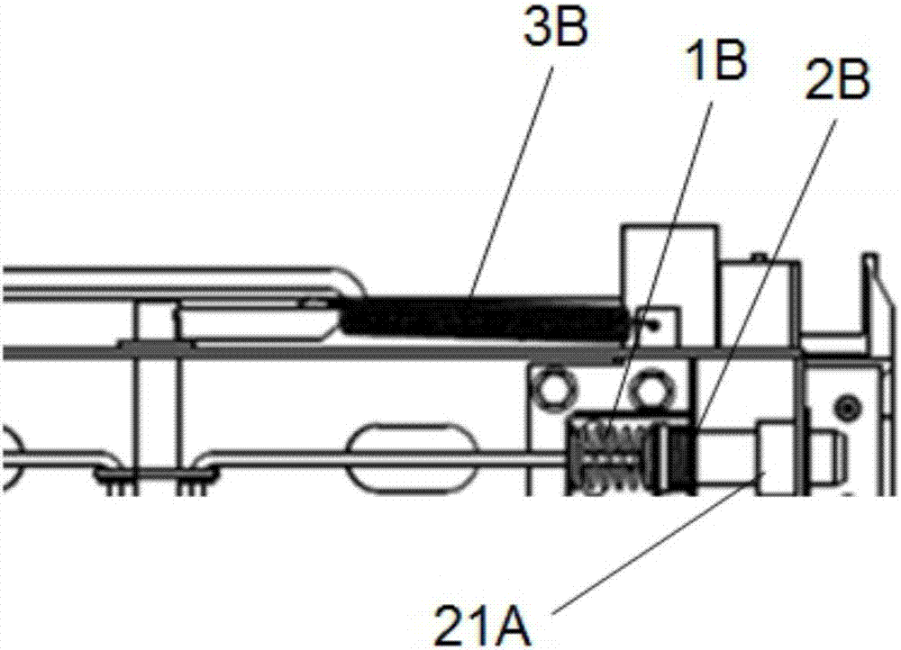
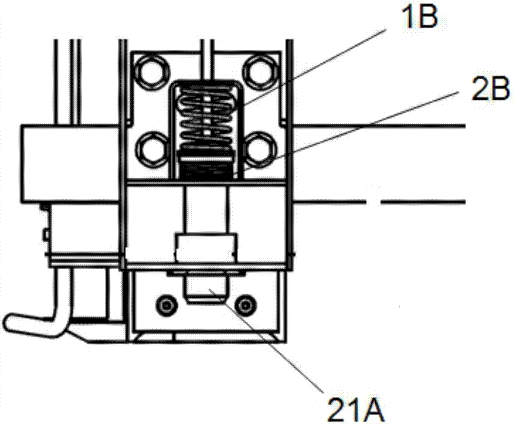
[0031] Such as Figure 4 , Figure 5 , Figure 6 and Figure 10 as shown, Figure 4 It is a top view of the zoom system of the carriage lock pin of the present invention; Figure 5 It is a partial cross-sectional view of the zoom system of the carriage lock pin in the present invention; Figure 6 is a partially enlarged view of M; Figure 10 is a side view of the locking pin. A sliding frame lock pin scaling system, comprising a base frame 1, two sets of lock pin mechanisms, and a drive rod 3; the two sets of lock pin mechanisms are respectively arranged at the front and rear ends of the base frame 1; each set of lock pin mechanisms includes two Two lock pin mechanisms, described two lock pin mechanisms are arranged on the symmetrical both sides of underframe; Described each lock pin mechanism comprises lock pin 8, outer spring 9, inner spring 10, extension spring frame 5, pull ring 6 , the pin spring sleeve 11 and the connecting rod 7; the locking pin 8 includes a prot...


PUM


Abstract

The invention relates to a carriage locking pin zoom system. The carriage locking pin zoom system comprises an under-frame, two sets of locking pin mechanisms and a driving rod. The two sets of locking pin mechanisms are arranged at the front and the back ends of the under-frame correspondingly, and each set of locking pin mechanism comprises two locking pin mechanisms; and the two locking pin mechanisms are arranged on the two sides of the under-frame symmetrically, and each locking pin mechanism comprises a locking pin, an outer spring, an inner spring, a tension spring frame, a pull ring, a pin spring sleeve and a connecting rod. The driving rod drives the tension spring frames to enable the four locking pins to conduct a linear reciprocating motion through rotation, the outer springs butt against the tension spring frames to enable the locking pins to extend out, and the inner springs butt against the pin spring sleeves to enable the locking pins to retract. The outer springs and the inner springs are arranged side by side, and control extension and retraction of the locking pins correspondingly, and extension force is provided by all the outer springs simultaneously. When clamping stagnation occurs on one locking pin, the extension force of all the outer springs is transmitted to the locking pin, greater extension force is provided, and the driving safety is improved sufficiently. When the locking pins retract, all the locking pins can retract independently, the situation that other locking pins cannot retract caused by one stuck locking pin is avoided, and the disassembly of a goods shelf is convenient.

Description

technical field [0001] The invention relates to the field of heavy vehicles, in particular to a sliding frame locking pin scaling system. Background technique [0002] Heavy truck is the abbreviation of heavy truck. This is an authentic, traditional, and informal appellation for heavy-duty trucks and semi-trailer tractors, including all kinds of special vehicles (sprinklers, fire engines, road cleaning vehicles, oil tankers) that you see on the road. , mixer trucks, etc.), dump trucks (dirt trucks, all with lifters), trucks (for cargo, including livestock, etc.), and some rare off-road vehicles (mostly for military use). [0003] At present, heavy trucks usually carry goods. As cities develop faster and faster, the pursuit of efficiency in loading and unloading heavy trucks is getting higher and higher. Therefore, a suspension carriage has appeared on the market, such as figure 1 As shown, a carriage 2A is set on the suspension system 1A, and retractable locking pins 21A a...

Claims


Application Information

Patent Timeline
IPC IPC(8): F16B21/12F16B21/14
CPCF16B21/12F16B21/14
Inventor 吴志强夏浩文黄怀宇王宇
Owner GUANGDONG FUWA HEAVY IND
Features
  • R&D
  • Intellectual Property
  • Life Sciences
  • Materials
  • Tech Scout
  • Unparalleled Data Quality
  • Higher Quality Content
  • 60% Fewer Hallucinations
Learn More