Method and apparatus for determining interval velocity under seismic scale

A layer velocity and scale technology, applied in the field of layer velocity determination, can solve problems such as low velocity, affecting seismic interpretation accuracy, affecting time-depth conversion accuracy, etc.

Active Publication Date: 2017-08-18
CHINA UNIV OF PETROLEUM (EAST CHINA)
View PDF13 Cites 10 Cited by
  • Summary
  • Abstract
  • Description
  • Claims
  • Application Information

AI Technical Summary

Problems solved by technology

Among them, the center frequency of acoustic logging is usually 10-20kHz, while the frequency range of seismic exploration is usually 5-100Hz. That is to say, there is a big difference between the frequency of acoustic logging and seismic exploration data. There is an obvious dispersion problem in the velocity of the data. The difference in velocity characteristics at two different frequencies leads to differences in synthetic seismic records, and also affects the time-depth conversion accuracy in the process of synthetic seismic records.
In addition, there is a large difference in the vertical resolution scale between well logging data and seismic data, and the direct production of synthetic seismic records at the well logging data scale will inevitably lead to a certain difference between well side channels at the seismic scale. Conducive to fine calibration and comparison of well seismic data
Moreover, in the actual production process, it is usually necessary to artificially stretch / compress or drift the synthetic seismic records, resulting in large errors in the calibration results, which affect the accuracy of seismic interpretation. The time-depth relationship cannot meet the accuracy of the wellside seismic trace calibration
[0003] To sum up, how to obtain the interval velocity that satisfies the calibration accuracy of side-hole seismic traces at the seismic scale is the key to solving the differences in scale and frequency characteristics between well logging data and seismic data and the low accuracy of conventional synthetic seismic record production methods

Method used


Image

  • Method and apparatus for determining interval velocity under seismic scale
  • Method and apparatus for determining interval velocity under seismic scale
  • Method and apparatus for determining interval velocity under seismic scale

Examples


Embodiment

[0144] In order to describe the features and working principle of the present invention more intuitively, a practical application scenario will be described below.

[0145] Such as Figure 7 As shown, it is a flow chart of this embodiment based on the finely synthesized seismic records of this case. include:

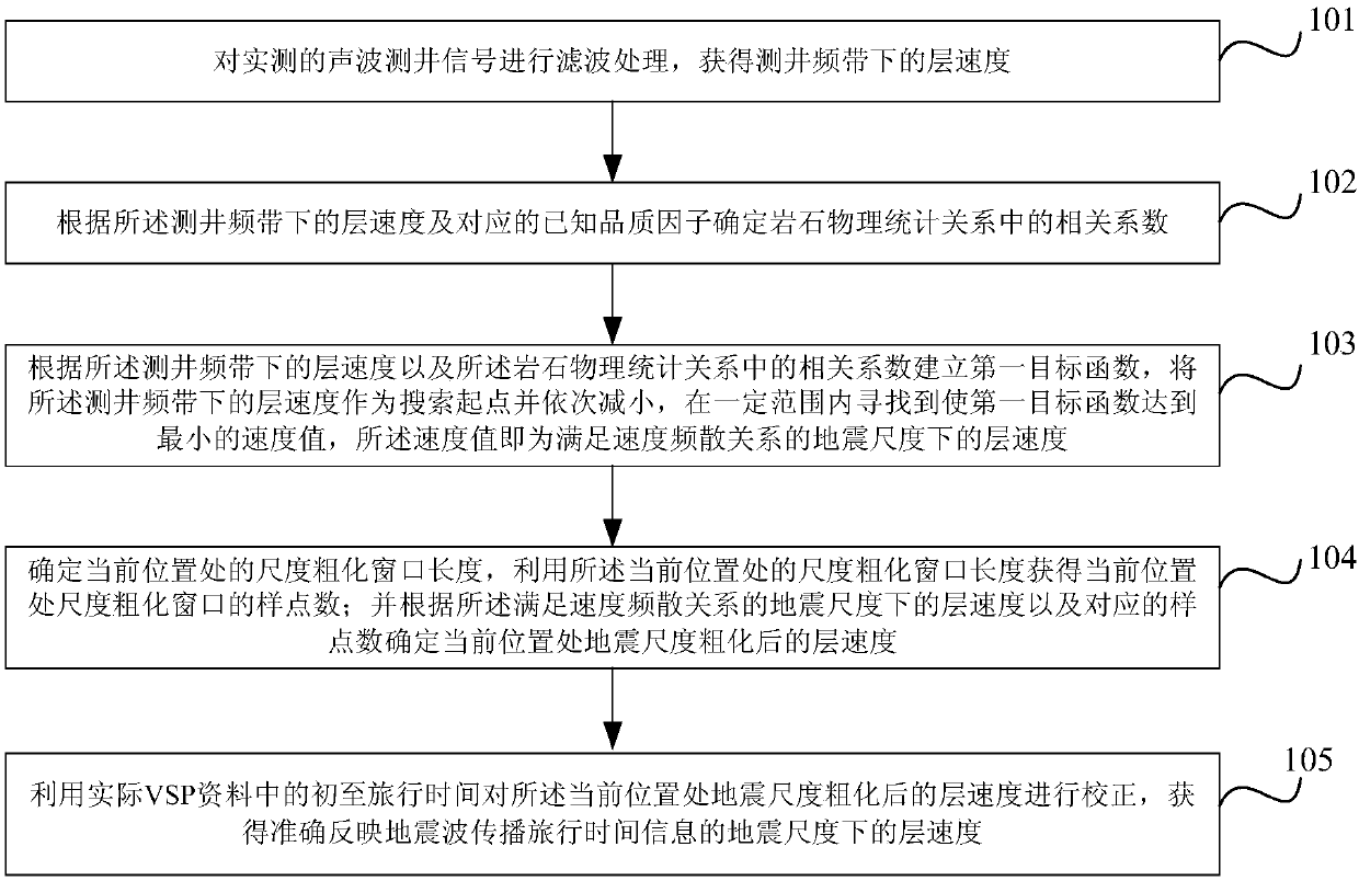
[0146] Step 1): Preprocessing of the acoustic logging signal to obtain the layer velocity under the logging frequency band;

[0147] Such as Figure 8Shown is the comparison chart of the data before and after the acoustic logging signal preprocessing. In the graph, data before preprocessing constitutes a solid line, and data after preprocessing constitutes a dotted line. The purpose of preprocessing is to correct the environment of acoustic logging curves, such as mud erosion correction and borehole diameter correction, etc., and to suppress or weaken the interference in the form of noise in the acquisition signal. The variable time window filter is used to preproce...


PUM


Abstract

The invention relates to a method and apparatus for determining an interval velocity under a seismic scale. The method includes the following steps that: an interval velocity under a logging frequency is obtained; a correlation coefficient in a rock physical statistic relation is determined according to the interval velocity under the logging frequency and a corresponding known quality factor; a first objective function is established according to the interval velocity under the logging frequency and the correlation coefficient in the rock physical statistic relation, and an interval velocity under the seismic scale, which satisfies a velocity dispersion relation, is obtained according to the first objective function; the length of a scale coarsening window at a current position is determined, the number of sampling points of the scale coarsening window at the current position is obtained through using the length of the scale coarsening window at the current position; and an interval velocity which has been subjected to seismic scale coarsening at the current position is determined according to the interval velocity under the seismic scale which satisfies the velocity dispersion relation and the number of the sampling points; and the interval velocity which has been subjected to seismic scale coarsening at the current position is corrected, so that the interval velocity under the seismic scale, which can accurately reflect the travel time information of seismic wave propagation can be obtained.

Description

technical field [0001] The invention relates to the technical field of petroleum geophysical exploration, in particular to a method and device for determining layer velocity under the seismic scale that can accurately reflect travel time information of seismic wave propagation. Background technique [0002] With the continuous deepening of oil and gas exploration and development, how to make full use of the high-resolution characteristics of well logging data in the vertical direction and the control ability of 3D seismic data in the lateral direction, and improve reservoir prediction and oil and gas identification under the constraints of limited logging data Reliability is an inevitable trend in the development of oil and gas seismic exploration technology. Well seismic calibration is a bridge for accurate cross-scale calibration of logging data and seismic data. Through the production of fine synthetic seismic records, the quantitative mapping between the elastic paramete...

Claims


Application Information

Patent Timeline
Patent Type & Authority Applications(China)
IPC IPC(8): G01V1/40G01V1/30G01V1/36
CPCG01V1/303G01V1/362G01V1/40G01V2210/6222G01V2210/52
Inventor 曹丹平
Owner CHINA UNIV OF PETROLEUM (EAST CHINA)
Why Eureka
Try Eureka