Compact continuous zooming optical system

An optical system and compact technology, applied in optics, optical components, instruments, etc., can solve the problems of miniaturization and high zoom ratio of the optical system, and achieve the effect of rapid zooming

Active Publication Date: 2017-08-18
西安中科飞图光电科技有限公司
View PDF14 Cites 5 Cited by
  • Summary
  • Abstract
  • Description
  • Claims
  • Application Information

AI Technical Summary

Problems solved by technology

[0010] The purpose of the present invention is to provide a compact continuous zoom optical system to solve the technical problem that the existing optical system is difficult to achieve miniaturization and high zoom ratio

Method used


Image

  • Compact continuous zooming optical system
  • Compact continuous zooming optical system
  • Compact continuous zooming optical system

Examples


Embodiment Construction

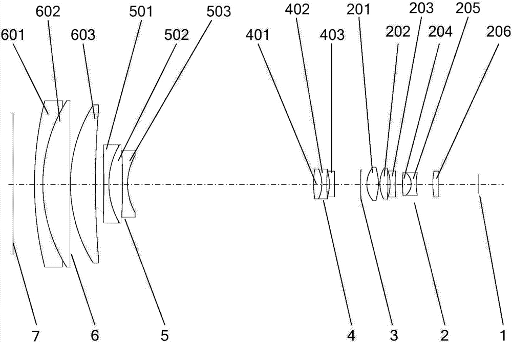
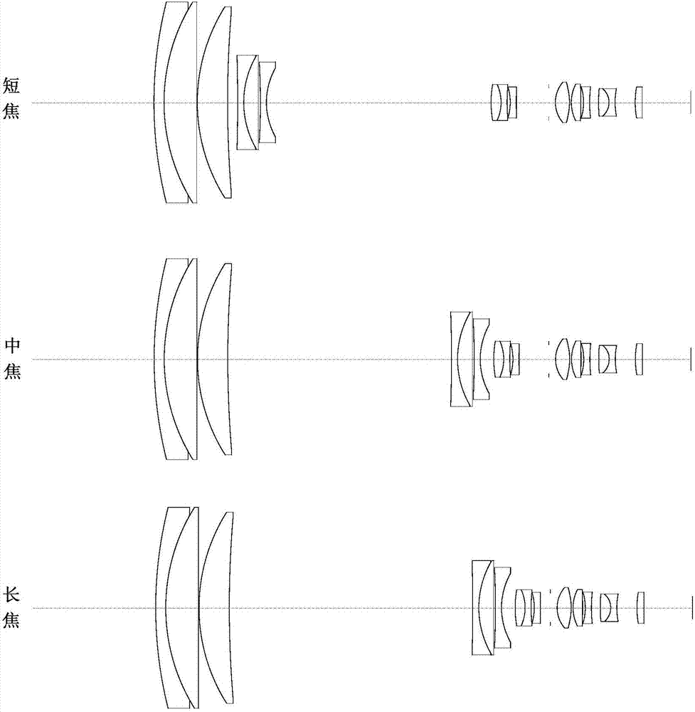
[0038] see figure 1 and figure 2 , the present invention provides a compact continuous zoom optical system, the structure of its preferred embodiment includes a front fixed lens group 6 with positive refractive power, a zoom lens group with negative refractive power, arranged in sequence from the object plane 7 to the focal plane 1 Multiplier lens group 5, compensation lens group 4 with negative refractive power, aperture 3 and rear fixed lens group 2 with positive refractive power. CCD, CMOS and other imaging devices are arranged on focal plane 1. The variable power mirror group 5 forms a complete imaging system together with the front fixed mirror group 6, the compensation mirror group 4 and the rear fixed mirror group 3. In the present invention, the total length of the system remains unchanged during the zooming process, and the position of the front fixed mirror group 6 is constant. The multiplier lens group 5 and the compensation lens group 4 move back and forth on the...


PUM


Abstract

The invention belongs to the photoelectric technical field, relates to a photographic object lens optical system, and specifically relates to a compact continuous zooming optical system. The optical system comprises a front fixed lens group, a zooming lens group, a compensation lens group, a diaphragm and a rear fixed lens group which are coaxially disposed in turn from an object plane to a focal plane. In the full zooming section range, the optical system can achieve high-definition imaging and a continuous zooming function for more than 20 times. All focal-length center view fields and edge view fields have good imaging quality in a continuous change process of a focal length. A zooming core composed of the zooming lens group and the compensation lens group moves continuously according to a movement rule given in design, and always moves back and forth on the optical axis during internal zooming; the aperture F number is constant while zooming, the total length is fixed, and the mass center has a small change; and the system is small in size, and the structure is compact.

Description

technical field [0001] The invention belongs to the field of photoelectric technology, and relates to a photographic objective lens optical system, in particular to a compact continuous zoom optical system. Background technique [0002] In recent years, the solid-state imaging sensors used for imaging detection have developed rapidly, and the detection sensitivity has been continuously improved. Large-area array and small-pixel image sensors have gradually become the mainstream, and the miniaturization, high-definition, and multi-purpose imaging equipment has become possible. The photographic objective optical system is the core of imaging equipment. In order to meet the increasingly stringent technical requirements of the market for miniaturized imaging equipment, especially for the upgrading of old products of photoelectric imaging load and the trial development of new products, small pixel high-sensitivity image sensors are used. Finally, the volume and weight of the imag...

Claims


Application Information

Patent Timeline
Patent Type & Authority Applications(China)
IPC IPC(8): G02B15/167
CPCG02B15/167
Inventor 曲锐曹剑中武力梅超彭建伟
Owner 西安中科飞图光电科技有限公司
Why Eureka
Try Eureka